
Aligning mechanism for vehicle couplers of rail vehicles and vehicle rescue method
A rail vehicle and centering mechanism technology, applied in the field of rail vehicles, can solve the problem that the coupler cannot be automatically connected, and achieve the effect of vehicle rescue
- Summary
- Abstract
- Description
- Claims
- Application Information
AI Technical Summary
Problems solved by technology
Method used
Image

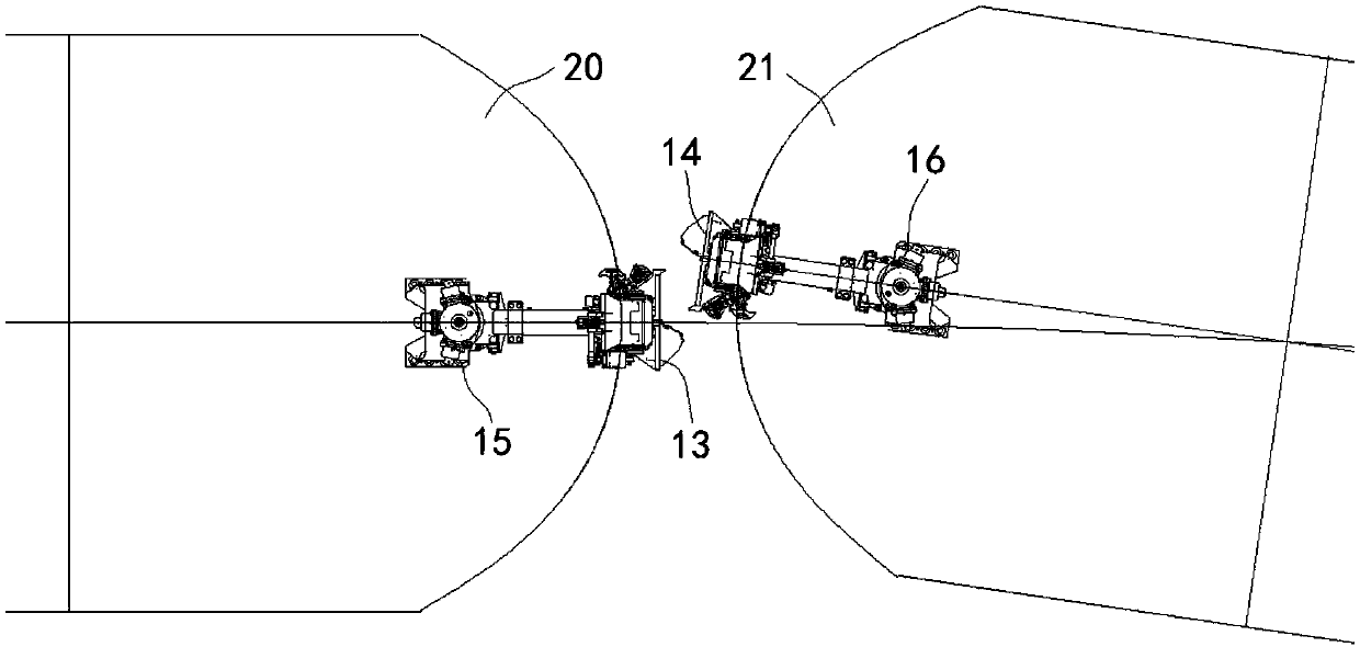
Examples
Embodiment 1
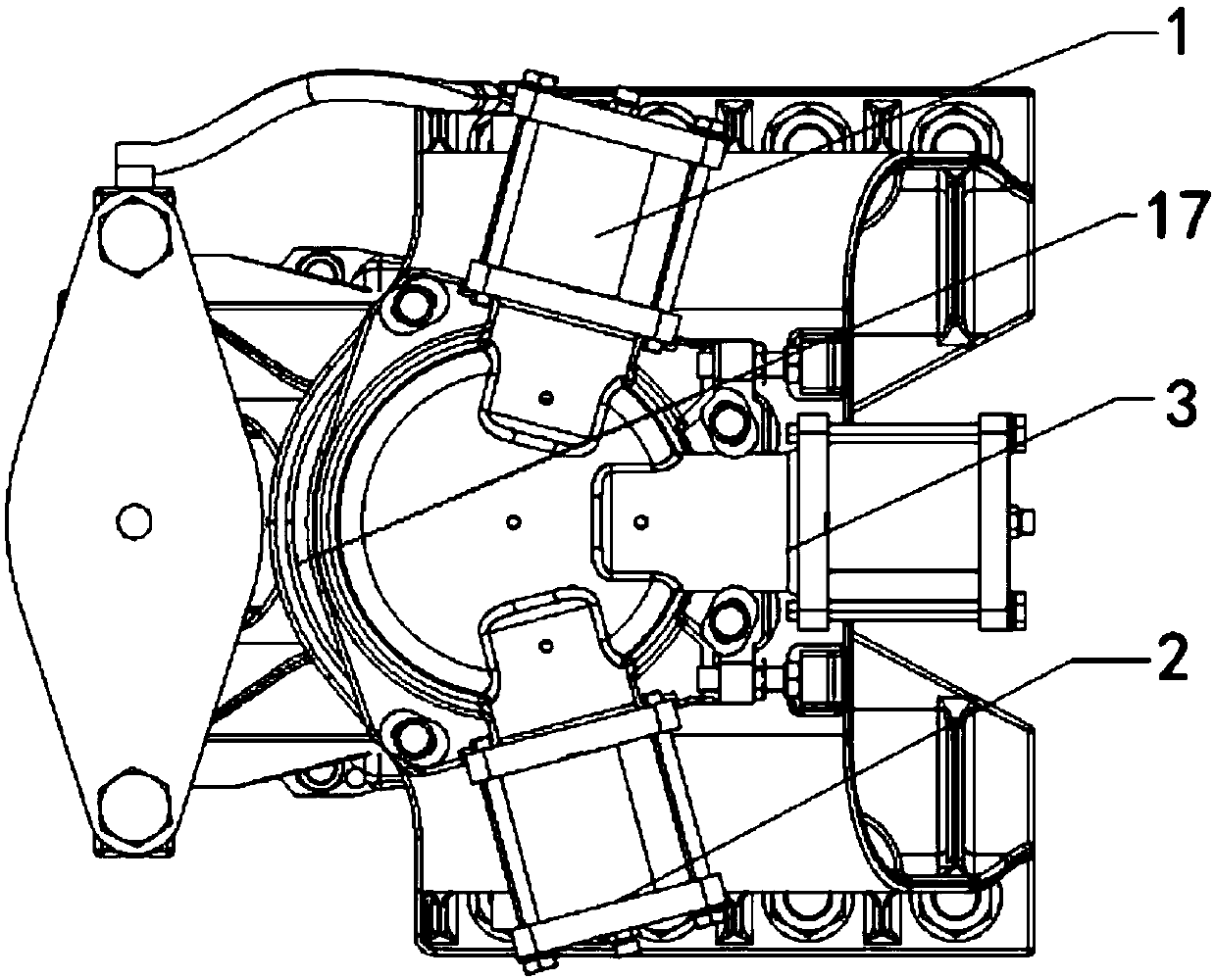
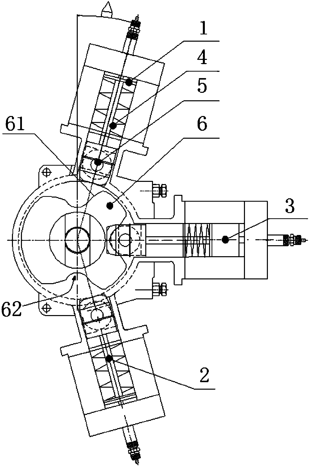
[0048] A rail vehicle coupler centering mechanism, such as Figure 2-4As shown, it includes a coupler buffer housing, a cam disc 6, a first cylinder 1, a second cylinder 2, a third cylinder 3, a cylinder piston rod 4 and a cylinder roller 5. The cam plate is connected with the coupler buffer housing through key grooves, fasteners and other components, so that the cam plate rotates to drive the coupler to rotate. The air duct of the vehicle inflates the corresponding cylinder to control the cylinder piston rod 4 to move forward. When the cylinder was in the non-ventilated state, the return spring in the cylinder moved the cylinder piston rod 4 backwards to reset, so that the cylinder roller and the cam disc were separated.
[0049] The cam plate 6 is fixedly connected with the coupler buffer housing 17 through key grooves and fasteners.
[0050] A first notch, a second notch and a third notch are provided on the outer peripheral surface of the cam disc 6 , and the sidewalls o...
Embodiment 2
[0058] A coupler centering mechanism, such as Figure 7-10 shown, which includes
[0059] Internal gear cam disc 32, which is used to be fixedly connected with the coupler buffer housing;
[0060] An external gear transmission mechanism 31, which is engaged with the internal gear cam disc 32 for transmission; and
[0061] A driving device, which is used to drive the external gear transmission mechanism 31 and / or the internal gear cam disc 32 to rotate an angle;
[0062] The internal gear cam disc 32 and / or the external gear transmission mechanism 31 are provided with a notch, and the outer side of the internal gear cam disc 32 is provided with a telescopic rod for keeping the center line of the coupler and the center line of the vehicle body in alignment;
[0063] When the telescopic rod stretches out, it cooperates with the notch, and the internal gear cam plate 32 and / or the external gear transmission mechanism 31 are locked together with the telescopic rod; The notch dis...
PUM
 Abstract
Description
Claims
Application Information