Double-spring type winding equipment

A double spring and equipment technology, applied in the field of online or tube winding, can solve the problems of unbalanced force on the runner, unsteady speed changes, large, and can only be set in the disk body at one end of the runner, etc. The effect of balanced distribution, balanced force and stable equipment

Pending Publication Date: 2018-02-09
JIANGSU HUITIAN ELECTROMECHANICAL TECH CO LTD
View PDF0 Cites 1 Cited by
  • Summary
  • Abstract
  • Description
  • Claims
  • Application Information

AI Technical Summary

Problems solved by technology

Traditional winding equipment is generally provided with a coil spring return part. Since the coil spring return part needs to provide sufficient return force, its radial dimension is generally large and can only be installed in the disc body at one end of the runner. The coil spring return part Acting on one end of the runner along the axial direction, the force on each position of the runner in the axial direction is seriously unbalanced, and the winding equipment is not stable enough and the speed changes greatly when recovering the water pipe

Method used


Image

  • Double-spring type winding equipment
  • Double-spring type winding equipment
  • Double-spring type winding equipment

Examples


Embodiment 1

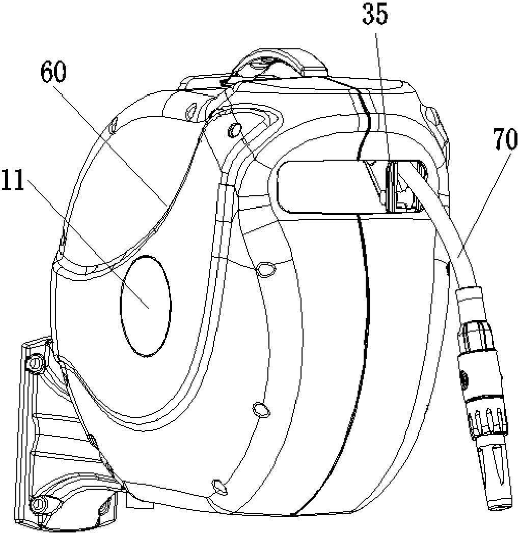
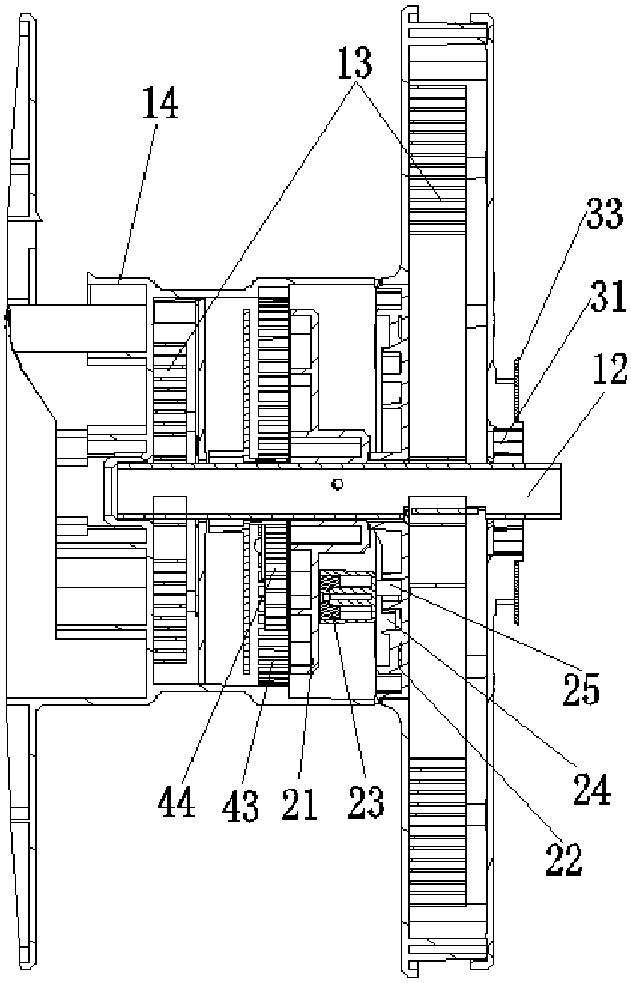
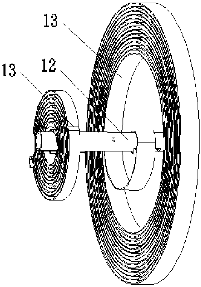
[0038] see Figure 1 to Figure 8 , a double spring winding device, including a support base 11, a support shaft 12, a coil spring 13 and a runner 14, the support shaft 12 is fixedly connected to the support base 11, the coil spring 13 is sleeved on the outside of the support shaft 12, and the coil spring The inner end of 13 is fixedly connected with the support shaft 12, and the runner 14 is sleeved on the outside of the support shaft 12 and the coil spring 13, and the runner 14 is respectively rotatably connected with the support shaft 12 and fixedly connected with the outer end of the coil spring 13 , An annular gap is formed between the support shaft 12 and the runner 14, two coil springs 13 are provided, and the two coil springs 13 are respectively arranged at different positions along the axial direction of the annular gap. By arranging the two coil springs 13 at two axial positions of the rotating wheel 14, the forces on each position of the rotating wheel 14 in the axia...

Embodiment 2

[0052] The rest are the same as in Embodiment 1, the difference is that a wire-releasing guide groove and a wire-receiving guide groove are provided on the opposite surface of the locking plate A, and the opposite surface of the locking plate B can be moved through a shaft part parallel to the support shaft. Rotate and connect a guide block.

Embodiment 3

[0054] The rest is the same as the first embodiment, except that the pay-off guide groove includes a section of the first groove bottom connected end to end, and the wire take-up guide groove includes a second groove bottom connected end to end.


PUM


Abstract

The invention discloses a double-spring winding device, which comprises a support seat, a support shaft, a coil spring and a runner, the support shaft is fixedly connected to the support seat, the coil spring is sleeved on the outside of the support shaft, and the inner end of the coil spring is connected to the The support shaft is fixedly connected, and the runner is sleeved on the outside of the support shaft and the coil spring, and the runner is respectively rotatably connected with the support shaft and fixedly connected with the outer end of the coil spring, and an annular gap is formed between the support shaft and the runner. There are two coil springs, and the two coil springs respectively correspond to different axial positions of the annular gap. By arranging the two coil springs at two positions along the axial direction of the runner, the force on each position of the runner in the axial direction is more balanced, and the winding equipment runs smoothly during use. At the same time, the radial dimension of each coil spring can be adjusted Appropriate shrinkage reduces the requirements for the installation position of the coil spring and ensures the installation space for two coil springs.

Description

technical field [0001] The invention relates to the field of coiling of wires or tubes, in particular to a double-spring coiling device. Background technique [0002] The winding equipment is used to store wires with a certain length, such as cables and pipes. When in use, the wire is pulled out to drive the runner to rotate forward for unwinding. After use, the coil spring reset part drives the runner. Reverse to wind up. Traditional winding equipment is generally provided with a coil spring return part. Since the coil spring return part needs to provide sufficient return force, its radial dimension is generally large and can only be installed in the disc body at one end of the runner. The coil spring return part Acting on one end of the runner along the axial direction, the force on each position of the runner in the axial direction is seriously unbalanced, and the winding equipment is not stable enough and the speed changes greatly when recovering the water pipe. Conte...

Claims


Application Information

Patent Timeline
Patent Type & Authority Applications(China)
IPC IPC(8): B65H75/38B65H75/44
CPCB65H75/38B65H75/4405B65H75/4434B65H75/4457B65H2701/33
Inventor 康海欣康海标唐骐亮
Owner JIANGSU HUITIAN ELECTROMECHANICAL TECH CO LTD
Why Eureka
Try Eureka