Movable door and its telescopic mechanism and switch method

A telescopic mechanism and a technology for moving doors, which is applied in the field of moving doors, can solve problems such as poor concealment and poor decoration effects, and achieve the effects of balanced force, compact structure, and precise positioning

Pending Publication Date: 2018-02-09
ZHEJIANG JINGGONG STEEL BUILDING GRP
View PDF6 Cites 9 Cited by
  • Summary
  • Abstract
  • Description
  • Claims
  • Application Information

AI Technical Summary

Problems solved by technology

[0003] In order to overcome the disadvantages of poor concealment and poor decoration effect of the traditional movable door

Method used


Image

  • Movable door and its telescopic mechanism and switch method
  • Movable door and its telescopic mechanism and switch method
  • Movable door and its telescopic mechanism and switch method

Examples


Embodiment Construction

[0018] In order to describe the structural characteristics and specific operation steps of the present invention in detail, the following specific embodiments are given together with the accompanying drawings for illustration.

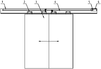
[0019] Such as figure 1 Shown, the present invention comprises a synchronous belt 1, four hangers 2, two single door leaves 3, a guide rail 4, two synchronous pulleys 5, a motor and a controller 6. Synchronous belt 1, hanger 2, single door leaf 3, synchronous pulley 5, motor and controller 6 are all arranged on guide rail 4.

[0020] The synchronous belt 1 is installed on the synchronous pulley 5, and the motor and the controller 6 drive the synchronous pulley 5 to drive the synchronous belt 1 to reciprocate. A single door leaf 3 is respectively connected to the upper and lower sides of the synchronous belt 1 through the hanger 2, and the movement of the synchronous belt 1 drives the door leaf 3 to move horizontally along the guide rail 4.

[0021] S...


PUM


Abstract

The invention discloses a movable door and its telescopic mechanism and switching method. The movable door comprises an upper cross beam and a lower cross beam, wherein a bidirectional screw rod is arranged between the upper cross beam and the lower cross beam, left and right rotary nuts are movably mounted on the bidirectional screw rod, a four-bar linkage is mounted on the left and right rotarynuts, and the two ends of the four-bar linkage are symmetrically provided with door panel connecting bases. The movable door further comprises a middle frame and a door panel frame, wherein the telescopic mechanism is mounted on the middle frame through the upper cross beam and the lower cross beam, and the door panel connecting bases are mounted on the door panel frame. The movable door is designed to overcome the defects of poor space partition concealing performance and poor decorative effect of the traditional movable door.

Description

technical field [0001] The invention belongs to the field of movable doors, and in particular relates to a movable door, a telescoping mechanism and a switch method thereof. Background technique [0002] Due to its simple structure, convenient use, and beautiful appearance, the induction sliding door has been widely used in the entrances of various shopping malls and office buildings. This type of mobile door is mainly composed of the following components: controller, sensor, motor, belt, guide rail, pulley, hanging parts, etc. When this type of door is working, when a person approaches the automatic door, the detection device (microwave signal, foot pad switch, infrared switch, light switch, etc.) installed on the inside and outside of the door will detect it, and then the signal will be sent to the control device. After receiving the signal, the control device drives the motor to rotate towards the opening direction of the door, and drives the reducer, pulley and belt to ...

Claims


Application Information

Patent Timeline
IPC IPC(8): E06B3/46E05D15/06E05F15/73E05F15/652
CPCE05D15/0652E05F15/652E05F15/73E06B3/4636
Inventor 邓伟平张小英俞荣华俞锡齐陈雄蒋勤丰
Owner ZHEJIANG JINGGONG STEEL BUILDING GRP
Why Eureka
Try Eureka