Shaft part strain gage sticking device

A technology for shaft parts and pasting devices, which is applied in the direction of measuring devices, connecting components, instruments, etc., can solve the problems that the quality and precision of strain gauge pasting cannot be guaranteed, and achieve high pasting efficiency, accurate pasting position, and high pasting quality Effect

Active Publication Date: 2018-02-09
GUANGZHOU UNIVERSITY
View PDF9 Cites 2 Cited by
  • Summary
  • Abstract
  • Description
  • Claims
  • Application Information

AI Technical Summary

Problems solved by technology

The above-mentioned invention patent scheme uses the workbench as the base, and puts all the tools required for pasting the strain gauges in the tool library, which provides convenient conditions for the pasting of the strain gauges, but obviously has the following disadvantages: 1. Due to the need for pasting The shaft parts of the strain gauge generally need to be installed on the corresponding working position first, and then the strain gauge is pasted. This device needs to install the shaft parts on its workbench separately; The pasting efficiency is high, which saves some manpower, but still cannot guarantee the quality and accuracy of the strain gauge pasting

Method used


Image

  • Shaft part strain gage sticking device
  • Shaft part strain gage sticking device
  • Shaft part strain gage sticking device

Examples


Embodiment Construction

[0023] The present invention will be further described in detail in conjunction with the accompanying drawings and specific embodiments.

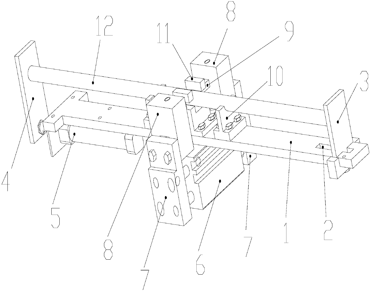
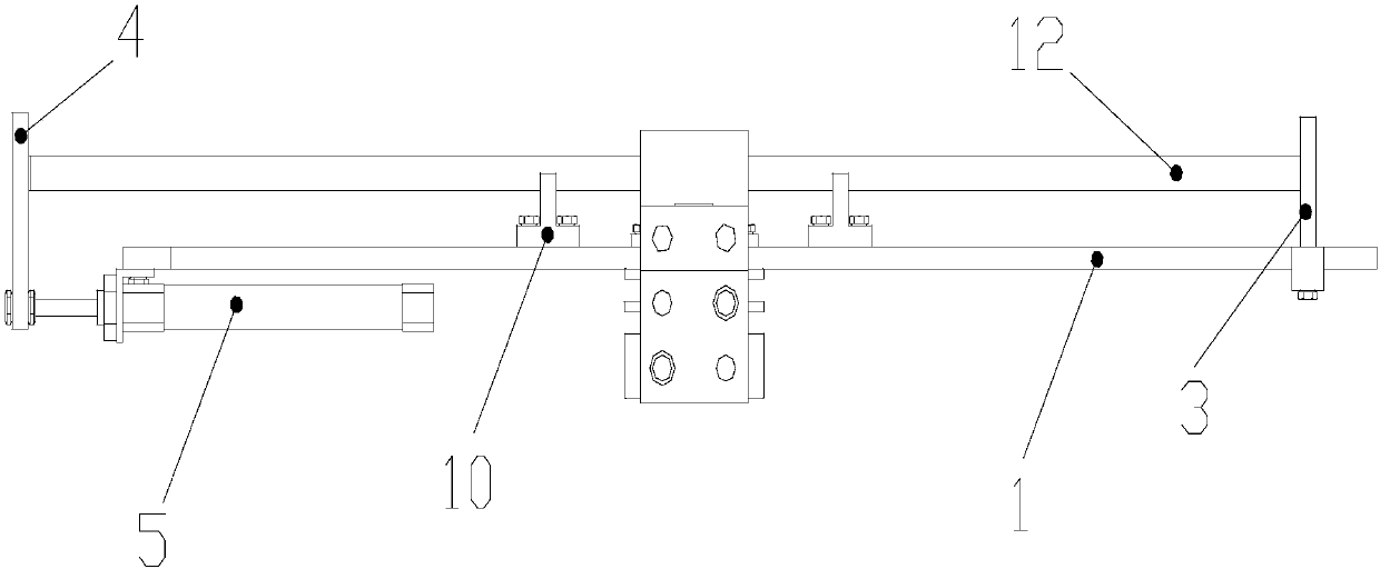
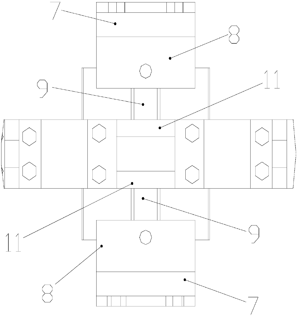
[0024] For the convenience of description, the directions mentioned below are explained as follows: the directions of up, down, left, and right mentioned below are related to figure 2 The up, down, left, and right directions are the same. The front and back directions mentioned below are the same as image 3 The up and down directions are the same; the left and right directions are the horizontal direction, and the front and rear directions are the longitudinal direction.

[0025] combine Figure 1 to Figure 7 As shown, a strain gauge sticking device for shaft parts includes a base plate, an axial positioning mechanism installed on the base plate, a vacuum absorber, an adsorption head, a two-way cylinder, and a positioner. The shaft parts placed along the transverse direction are installed on the axial positioning mechanism, that is, the...


PUM


Abstract

The invention relates to a shaft part strain gage sticking device. A shaft part arranged in the transverse direction is mounted on an axial locating mechanism. A locator is fixed to the upper end faceof a base plate and provided with a transverse channel used for allowing the shaft part to penetrate. Containing grooves used for containing stress gages are formed in the locator, and the containinggrooves are located in the side of the shaft part. A bidirectional air cylinder used for driving vacuum adsorbers to move longitudinally is mounted on the lower end face of the base plate. An adsorption head is mounted on each vacuum adsorber. A vertical through hole is formed in each vacuum adsorber, a longitudinal through hole is formed in each adsorption head, and the longitudinal through holes communicate with the vertical through holes. Each adsorption head is provided with an arc face matched with the circumferential side face of the shaft part. Along with movement of the vacuum adsorbers, the adsorption heads penetrate the containing grooves and are attached to the circumferential side face of the shaft part. The sticking device is high in sticking quality and sticking efficiency and accurate in sticking position and belongs to the technical field of shaft part strain gage sticking.

Description

technical field [0001] The invention relates to the technical field of sticking strain gauges of shaft parts, in particular to a sticking device for strain gauges of shaft parts. Background technique [0002] Electrical measurement is one of the commonly used experimental and testing methods in engineering structures. By pasting the strain gauge on the corresponding part of the test piece, the strain value of the measured point is converted into the resistance change of the strain gauge, and the corresponding stress value can be obtained by calculating the resistance change rate. However, in the electrical measurement method, the sticking quality of the strain gauge has a great influence on the experimental results. Traditional strain gauges are pasted manually, which not only consumes a lot of time, but also has defects such as uneven thickness of the pasting layer due to inconsistent pressure, great harm to the human body caused by the glue used for pasting, and poor past...

Claims


Application Information

Patent Timeline
Patent Type & Authority Applications(China)
IPC IPC(8): F16B11/00G01L1/22
CPCF16B11/006G01L1/22
Inventor 黄文恺浣石何俊峰肖颖江吉昌庞书孟吴羽
Owner GUANGZHOU UNIVERSITY
Why Eureka
Try Eureka