Assembly process for magnetic cores and substrates of surface mounting type power inductors

A power inductor and assembly process technology, applied in the direction of transformer/inductor magnetic core, inductor/transformer/magnet manufacturing, circuit, etc., can solve the problems of finished product electrical parameters, sticking deviation and sticking crooked, defective products, etc., to achieve sticking The effect of good quality and high production efficiency

Active Publication Date: 2013-02-13
广东昭信智能装备有限公司
View PDF6 Cites 2 Cited by
  • Summary
  • Abstract
  • Description
  • Claims
  • Application Information

AI Technical Summary

Problems solved by technology

Although this method is very simple, only relying on the operator to use his hands cannot ensure that the magnetic core is just pasted on the center of the negative, and there are often sticking deviations and crooked phenomena, which will cause cer

Method used


Image

  • Assembly process for magnetic cores and substrates of surface mounting type power inductors

Examples


Embodiment Construction

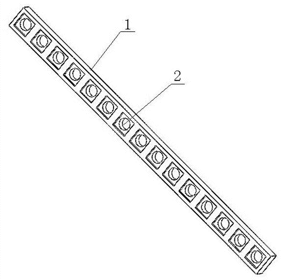
[0009] Attached below figure 1 The present invention is described further:

[0010] The assembly process method of the patch type power inductor magnetic core and the film includes the following steps: Step 101: cleaning a plurality of auxiliary rods 1, each auxiliary rod 1 is provided with a plurality of holes for placing the power inductor skeleton Groove 2, the magnetic core of the skeleton is located at the bottom of the groove 2, and the bottom sheet of the skeleton is positioned at the top of the groove 2, and a plurality of auxiliary rods 1 that are cleaned are placed side by side according to their grooves 2 facing upwards in a non-ferromagnetic The bottom of the container made of material; step 102: pour the magnetic core on the auxiliary rod 1 in the container; step 103: shake the container to make the magnetic core discharge into the groove 2 of the auxiliary rod; step 104: pour the undischarged The remaining magnetic cores that go into the groove 2 are taken out a...


PUM


Abstract

The invention discloses an assembly process for magnetic cores and substrates of surface mounting type power inductors. The assembly process comprises the steps of filling the bottom of a container with auxiliary rods; pouring magnetic cores into the container; shaking the container to enable the magnetic cores to be arranged in grooves of the auxiliary rods; withdrawing the remaining magnetic cores; filling the magnetic cores in the empty cavities; rearranging the magnetic cores that are not arranged well; opening glue grooves of spreaders, and placing in and fixing the auxiliary rods; withdrawing and rearranging the whole auxiliary rods if the magnetic cores are inclined; shifting the glue to front ends of spreading blocks, and fixing the spreading blocks; spreading glue; arranging the auxiliary rods horizontally; pasting substrates; placing the auxiliary rods into grooves of pressing rod clamps; aligning and overlapping upper pressing rods with the auxiliary rods; placing the rods back into the grooves of the pressing rod clamps after the rods change positions up and down; taking up the auxiliary rods; performing visual inspection on the magnetic cores; and placing the upper pressing rods qualified through the visual inspection into a tunnel kiln for drying. Compared with the prior art, the assembly process for magnetic cores and substrates of surface mounting type power inductors solves problems of poor pasting quality and low production efficiency of prior manual magnetic core pasting on substrates.

Description

technical field [0001] The invention relates to the technical field of manufacturing electronic components, in particular to a method for manufacturing a chip-type power inductor. Background technique [0002] Among the SMD power inductors manufactured by our company, one of the inductor skeletons is composed of an "I"-shaped magnetic core and a negative film pasted on the magnetic core. The assembly of the magnetic core and the negative film mentioned above is all manually completed one by one by the operator. The operator first smears glue on the top of a magnetic core by hand, and then pastes a negative film on the glue surface of the magnetic core. Although this method is very simple, only relying on the operator to use his hands cannot ensure that the magnetic core is just pasted on the center of the negative, and there are often sticking deviations and crooked phenomena, which will cause certain damage to the electrical parameters of the finished product. The impact ...

Claims


Application Information

Patent Timeline
IPC IPC(8): H01F41/00H01F41/02H01F27/26
Inventor 姜普杨春李培涛
Owner 广东昭信智能装备有限公司
Why Eureka
Try Eureka