Fast Tilt Phase Error Compensation Method and Device Based on Wavefront Rotation

A tilt phase and error compensation technology, applied in measurement devices, optical devices, instruments, etc., can solve the problems of being easily affected by noise, unable to eliminate the tilt error of off-axis structures, affecting the accuracy of quantitative phase, etc., to achieve fast and accurate Effect of tilt phase error compensation

Active Publication Date: 2019-12-31
SHENZHEN UNIV
View PDF6 Cites 0 Cited by
  • Summary
  • Abstract
  • Description
  • Claims
  • Application Information

AI Technical Summary

Problems solved by technology

However, the off-axis structure will introduce a tilt phase factor, resulting in a certain angle of tilt error in the reconstruction phase, which affects the accuracy of quantitative phase measurement; the coaxial structure in the coaxial holographic microscope system cannot eliminate the tilt error introduced by the off-axis structure. Tilt errors can only be removed by numerical compensation methods, so in order to obtain accurate object phase information, it is necessary to perform tilt phase error compensation on the reconstructed phase
[0004] In order to eliminate the off-axis tilt in the coaxial digital holographic microscope, someone proposed the spectral center translation method, which translates the spectrum of the virtual image to the center of the spectrum in the hologram spectrum, thereby eliminating the off-axis tilt, but the accuracy of the positioning of the spectral center is limited to the whole pixels, it is necessary to further remove the residual skew distribution
It was proposed to use the numerical compensation method of the phase template to eliminate the off-axis tilt. The phase template can be obtained from the pre-knowledge of the system or the acquisition of a sample-free hologram, but this method needs to know the parameters of the system in advance, or need to acquire two holograms. Suitable for dynamic measurement
Some people propose to use the polynomial fitting method to eliminate the off-axis tilt. This method requires additional numerical fitting calculations, increases the amount of calculations, and is susceptible to noise

Method used


Image

  • Fast Tilt Phase Error Compensation Method and Device Based on Wavefront Rotation
  • Fast Tilt Phase Error Compensation Method and Device Based on Wavefront Rotation
  • Fast Tilt Phase Error Compensation Method and Device Based on Wavefront Rotation

Examples


Embodiment Construction

[0039] In order to make the object, technical solution and advantages of the present invention clearer, the present invention will be further described in detail below in conjunction with the accompanying drawings and embodiments. It should be understood that the specific embodiments described here are only used to explain the present invention, not to limit the present invention.
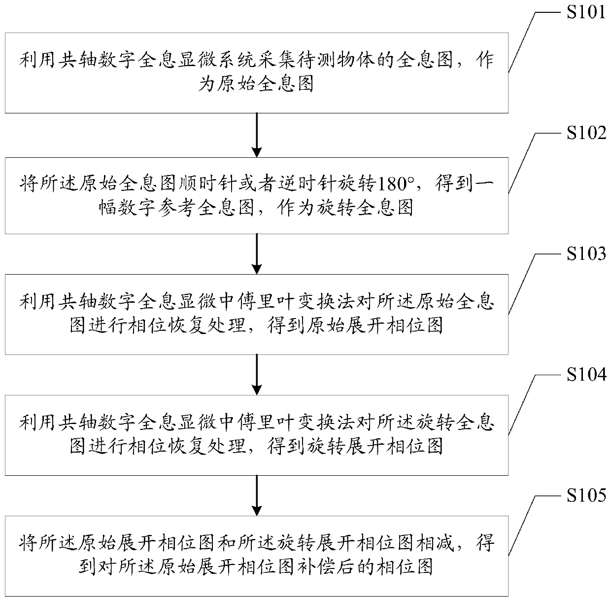
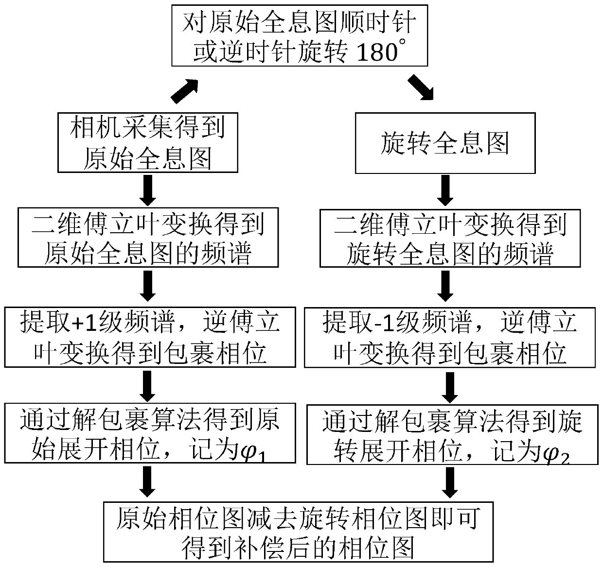
[0040] The main realization idea of ​​the present invention is as follows: first, the hologram of the object to be measured is collected by the coaxial digital holographic microscope system as the original hologram; then the original hologram is rotated 180° clockwise or counterclockwise to obtain a new Hologram, as a rotating hologram; extract the +1-level spectrum from the original hologram to obtain the original unfolded phase map; extract the -1-level spectrum from the rotating hologram to obtain the rotated unfolded phase map; combine the original unfolded phase map and the rotated unfolded pha...


PUM


Abstract

The present invention is applicable to the technical field of optical imaging correction, and provides a fast tilt phase error compensation method and device based on wavefront rotation, comprising: collecting, by using a coaxial digital holographic microscopy system, a hologram of an object to be measured as an original hologram; rotating the original hologram by 180 degrees clockwise or counterclockwise to obtain a digital reference hologram as a rotary hologram; performing phase recovery processing on the original hologram by using a Fourier transform method in the digital holographic microscopy, so as to obtain an original expansion phase diagram φ1; performing phase recovery processing on the rotary hologram by using the Fourier transform method in the digital holographic microscopy, so as to obtain a rotary expansion phase diagram φ2; and subtracting the rotary expansion phase diagram φ2 from the original expansion phase diagram φ1, so as to obtain a phase diagram after compensation for the original expansion phase diagram. The method provided by the present invention realizes fast and accurate tilt phase error compensation in the coaxial digital holographic microscopy imaging.

Description

technical field [0001] The invention belongs to the technical field of optical imaging correction, in particular to a fast tilt phase error compensation method and device based on wavefront rotation. Background technique [0002] As a quantitative phase measurement technology, digital holographic microscopy can obtain quantitative amplitude information and phase information of the object to be measured with only a single hologram, and has the advantages of non-contact, label-free, high resolution, and low cost. Among them, the coaxial digital holographic microstructure is often used in the quantitative measurement of cells and micro-optical components because of its high time stability and compact characteristics. The characteristic of the coaxial digital holographic microscope system is that the optical path of the object light and the optical path of the reference light go through the same optical path, so this structure can not only maintain the stability of the system, b...

Claims


Application Information

Patent Timeline
Patent Type & Authority Patents(China)
IPC IPC(8): G01B9/04G01B9/021
CPCG01B9/021G01B9/04
Inventor 彭翔邓定南何文奇吴禹刘晓利
Owner SHENZHEN UNIV
Why Eureka
Try Eureka