Supercharge Your Innovation With Domain-Expert AI Agents!

Development box

A developing cartridge and gear technology is applied in the field of developing cartridges, which can solve the problems of bumping and breakage of the sensor gear 70 of the external tooth 77, and achieve the effect of preventing gear breakage.

Active Publication Date: 2018-02-09
ZHONGSHAN KINGWAY IMAGE TECH CO LTD
View PDF5 Cites 1 Cited by
  • Summary
  • Abstract
  • Description
  • Claims
  • Application Information

AI Technical Summary

Problems solved by technology

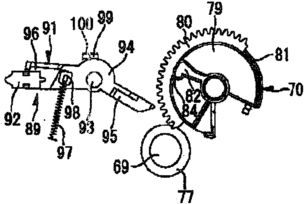
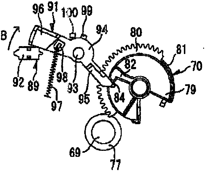
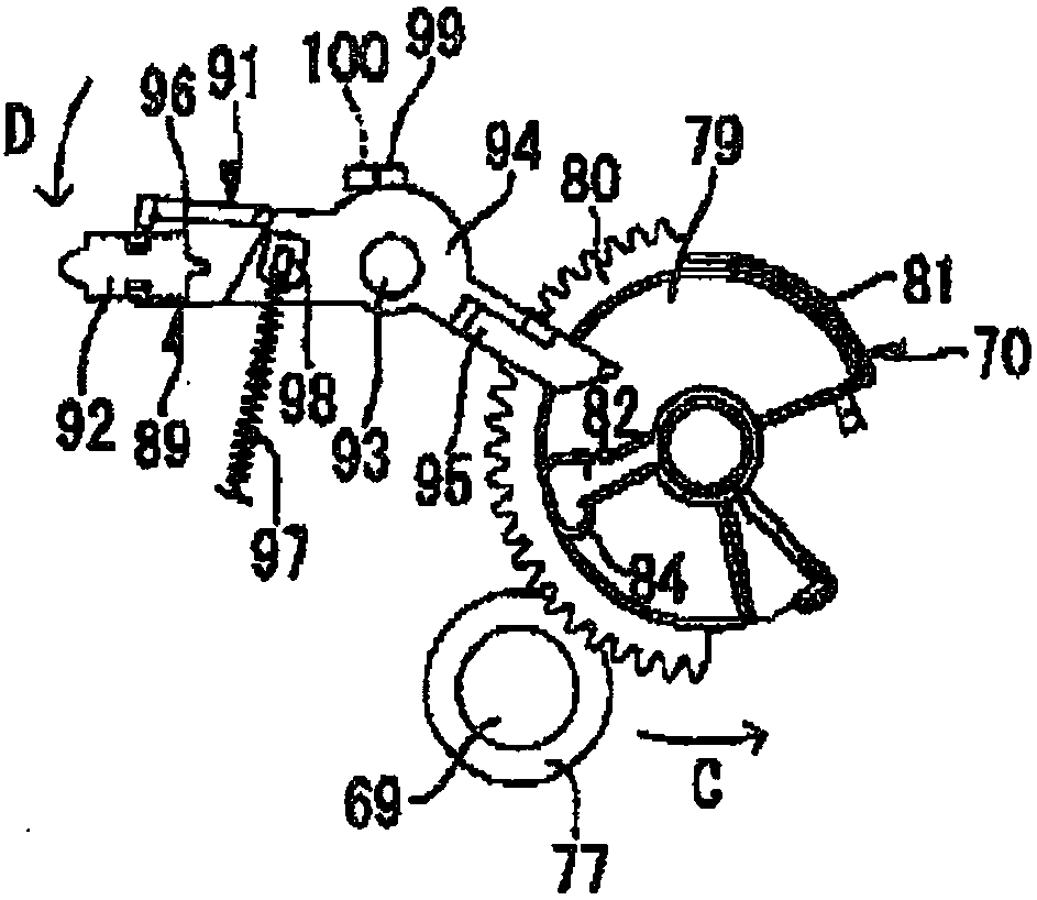
[0008] like Figure 1D As shown, after the counting mechanism completes the counting work, although the outer teeth 77 are no longer meshed with the sensor gear 70, the two are still very close. During the transportation of the developing cartridge, it is inevitable that bumps will occur. At this time, The outer teeth 77 will collide with the sensor gear 70, and in the process, the outer teeth 77 or the sensor gear 70 may break

Method used


Image

  • Development box
  • Development box
  • Development box

Examples


Embodiment Construction

[0048] Describe the embodiment of the present invention in detail below in conjunction with accompanying drawing; For more clearly describing the embodiment of the present invention, do following definition before beginning to describe: define the length direction of developing cartridge as vertical X, the width direction of developing cartridge is horizontal Y, developing The height direction of the box is vertical Z.

[0049] [Overall structure of developing cartridge]

[0050] figure 2 It is a schematic diagram of the overall structure of the developing cartridge viewed from the driving end of the present invention; image 3 It is a schematic diagram of the overall structure of the developing cartridge viewed from the conductive end of the present invention; Figure 4 It is a schematic diagram of the overall structure of the developing cartridge viewed from the front end of the present invention.

[0051] As shown in the figure, the developing cartridge P includes a cas...


PUM


Abstract

The invention relates to a development box comprising a shell, and a driving gear and a counting mechanism, which are arranged at the longitudinal tail end of the shell and are combined with each other, wherein the driving gear comprises a first gear and a second gear, which are combined with each other, and a contact part; the counting mechanism comprises a counting member, an intermediate member, a power receiving member and a separation component, the separation component comprises a separation member and a translation component, which are combined with each other, the translation componentis combined with the shell, and the separation member is combined with the power receiving member and is opposite to the contact part; the separation member comprises a cam opposite to the contact part, prior to the counting, the distance LMQ between a point Q closest to the contact part of the cam and the rotation center M of the separation member is greater than the distance LNT between the point T closest to the contact part of the cam and the rotation center after the counting, the rotation center of the separation member is changed via the cam, so that the rotation center of the separation member prior to the counting is further away from the contact part than the rotation center of the separation member after the counting, therefore even if the development box is collided, the two components is not in contact with each other.

Description

technical field [0001] The invention relates to the field of electrophotographic imaging, in particular to a developing box detachably installed in an electrophotographic imaging device. Background technique [0002] At present, in the field of electrophotographic imaging, laser printing is a common office method. In order to reduce the cost of end users, some printer manufacturers have separately installed the drum assembly that forms the electrostatic latent image in the printer and the developer cartridge that contains the developer. The service life of the drum assembly is designed to be long, and when the developer in the developer cartridge is used up, the end user only needs to replace the corresponding developer cartridge. [0003] In order to inform the end users in time that the service life of the developing cartridge is about to end, each manufacturer considers installing a developing cartridge life detection device on the developing cartridge, one of which is to...

Claims


Application Information

Patent Timeline
IPC IPC(8): G03G15/08G03G21/16
CPCG03G15/08G03G21/1676
Inventor 蒲宏礼
Owner ZHONGSHAN KINGWAY IMAGE TECH CO LTD
Features
  • R&D
  • Intellectual Property
  • Life Sciences
  • Materials
  • Tech Scout
  • Unparalleled Data Quality
  • Higher Quality Content
  • 60% Fewer Hallucinations
Learn More