Printer Fault Control System

A fault control and printer technology, applied in the direction of electrical testing/monitoring, etc., can solve the problems of motor control MCU burning, rising, and low function coverage

Inactive Publication Date: 2019-10-18
台州市黄岩威瑞特模具有限公司
View PDF3 Cites 0 Cited by
  • Summary
  • Abstract
  • Description
  • Claims
  • Application Information

AI Technical Summary

Problems solved by technology

[0003] However, this method has low functional coverage: due to the limitation of the shape of the printed file and the printing speed, the motion control in the traditional test process cannot cover any motion path based on any motion rate. Therefore, it cannot be guaranteed that the printer has not printed before printing a certain There will be an abnormal situation caused by the firmware, and the current will flow to the main line of the main control circuit of the printer through the drive circuit, causing the main line voltage of the main control circuit of the printer to rise rapidly. If the alarm is not stopped in time, it will cause motor control. MCU burnout

Method used


Image

  • Printer Fault Control System
  • Printer Fault Control System
  • Printer Fault Control System

Examples


Embodiment Construction

[0034] The present invention will be further described below in conjunction with specific embodiment:

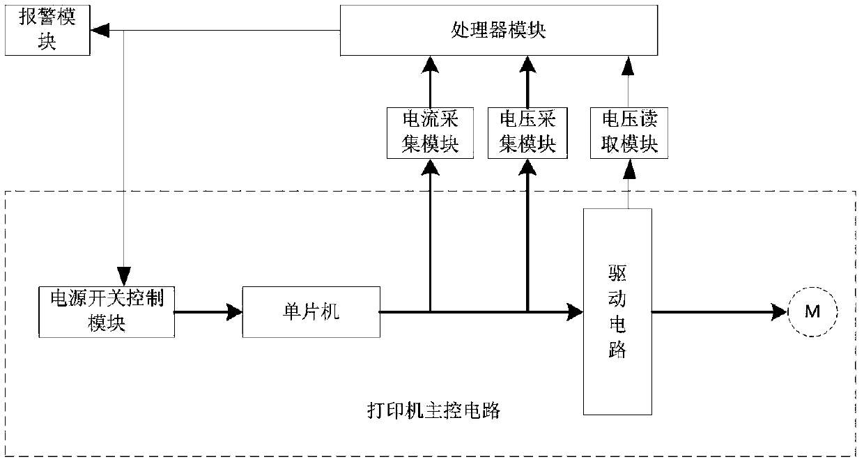
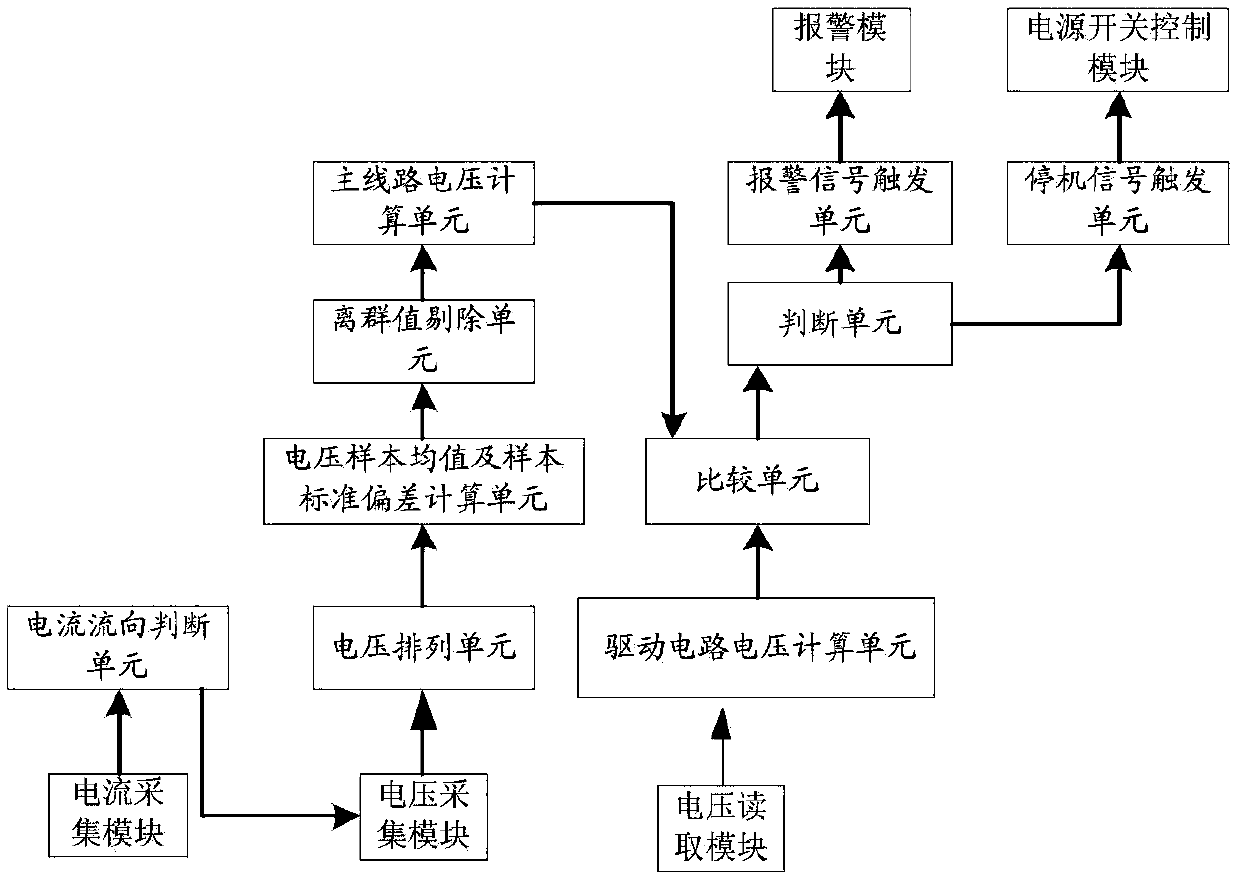
[0035] A printer failure control system according to the present invention includes an alarm module, a processor module, a current acquisition module, a voltage reading module and a voltage acquisition module, one signal output end of the processor module is connected to the signal input end of the alarm module, and the The other signal output end of the processor module is connected to the signal input end of the power switch control module in the main control circuit of the printer, and the signal output end of the current acquisition module, the voltage reading module and the voltage acquisition module are connected to the signal output end of the processor module. The input ends are connected, the signal acquisition ends of the current acquisition module and the voltage acquisition module are connected to the main line of the main control circuit of the printer, and the s...


PUM


Abstract

The invention discloses a printer fault control system, which comprises an alarm module, a processor module, a current acquisition module, a voltage reading module and a voltage acquisition module. The printer fault control system avoids fast rising in voltage of a main line of a printer main control circuit, stops and alarms in time and does not result in the burning of a motor control single-chip microcomputer.

Description

technical field [0001] The invention belongs to the field of new generation information technology, and in particular relates to a printer failure control system. Background technique [0002] At present, manufacturers of digital printing devices modify the open-source firmware to adapt to their own models. After the prototype is developed, the functional test is mainly based on traditional visual inspection, that is, to observe and collect its abnormal status through repeated printing. [0003] However, this method has low functional coverage: due to the limitation of the shape of the printed file and the printing speed, the motion control in the traditional test process cannot cover any motion path based on any motion rate. Therefore, it cannot be guaranteed that the printer has not printed before printing a certain There will be an abnormal situation caused by the firmware, and the current will flow to the main line of the main control circuit of the printer through the d...

Claims


Application Information

Patent Timeline
Patent Type & Authority Patents(China)
IPC IPC(8): G05B23/02
Inventor 万金钢
Owner 台州市黄岩威瑞特模具有限公司
Why Eureka
Try Eureka