
Rendering plotting method for replacing specific part material based on three-dimensional model

A 3D model and material technology, applied in image enhancement, image data processing, 3D image processing, etc., can solve the problem that materials cannot be partially replaced, and achieve easier control of design style, realistic renderings, and simple and quick replacement process Effect

Active Publication Date: 2018-02-09
SHENZHEN BINCENT TECH
View PDF7 Cites 11 Cited by
  • Summary
  • Abstract
  • Description
  • Claims
  • Application Information

AI Technical Summary

Problems solved by technology

The realization principle of the existing model color change function is to make multiple copies of the model, and each copy uses a different material, the user can only choose within a limited range, and cannot partially replace the material according to the part of the model

Method used


Image

  • Rendering plotting method for replacing specific part material based on three-dimensional model
  • Rendering plotting method for replacing specific part material based on three-dimensional model
  • Rendering plotting method for replacing specific part material based on three-dimensional model

Examples


Embodiment 1

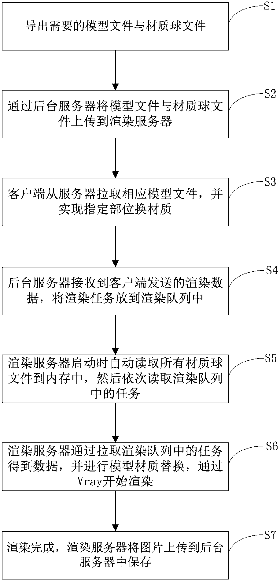
[0051] Such as figure 1 As shown, the method includes the following steps:

[0052] S1. Export required model files and shader files as the basic data source of rendering objects and texture map objects. In the preferred embodiment of the present invention, the model file and the shader file are exported by the three-dimensional software 3Dmax. The steps to create a shader file are: open the [Material Editor] window, select the first shader, modulate a "mahogany floor" material, and then click the [Get Material] button, in the pop-up [Material / Map Browser] dialog In the box, select [Mtl Library] on the left side of the window, and click the [Save As] button. If there are materials in the [Material / Map Browser] dialog box, click the [Clear Material Library] button to delete all the current materials. In the pop-up [SaveMaterialLibrary] dialog box, select a path, enter "Material File Library" in the [File Name] text box, and then click the [Save] button.

[0053] After saving, a n...

Embodiment 2

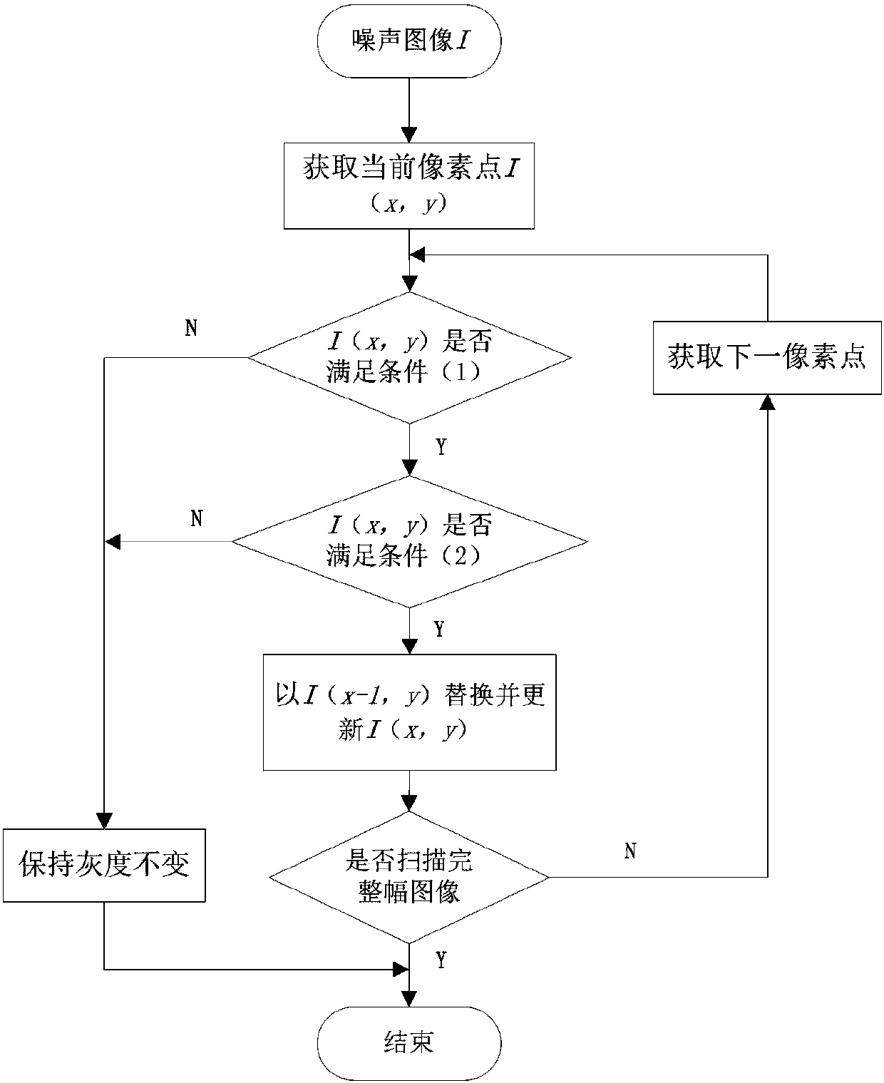
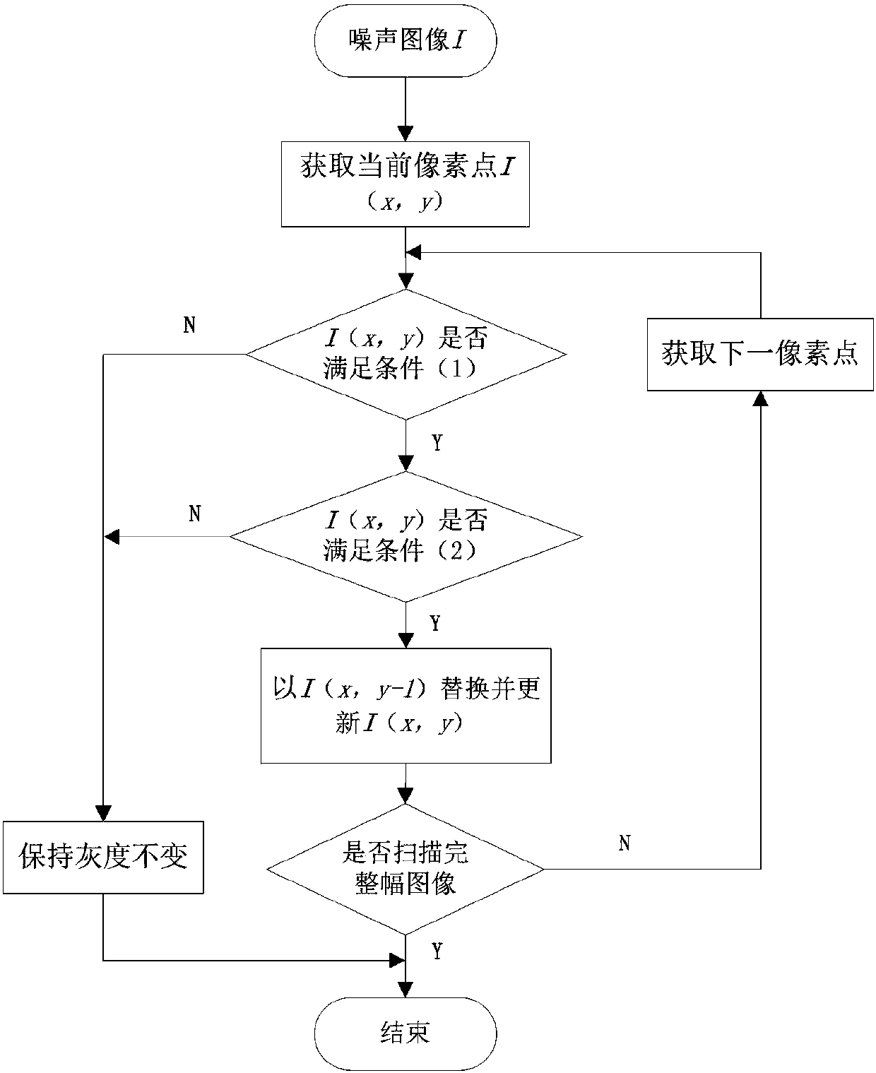
[0094] In the second embodiment of the present invention, the difference from the first embodiment is that the judgment condition (2) for judging whether the current pixel point I(x, y) on the image is a noise pixel can also be: D<I (x, y-1)<T, the value range of the weight coefficient w is: 0.3≤w≤0.45, specifically, the value of the weight coefficient w is preferably 0.3 or 0.45. Except for this, the other technical features of the second embodiment are the same as those of the first embodiment.

[0095] In summary, the method of the present invention can replace any material with any part, rendering is more flexible, and the unity of design style is easier to control. The material replacement process of the specified part is to obtain the corresponding texture name through the currently selected Surface surface, and through the established correspondence between the texture name of the diffuse material and the Surface, find all the Surfaces with this texture name, and map them ...


PUM


Abstract

The invention discloses a rendering plotting method for replacing a specific part material based on a three-dimensional model, and relates to the field of computer graphic image rendering. The methodcomprises the steps: exporting needed model files and material ball files; uploading the model files and the material ball files to a rendering server through a background server; enabling a client toextract the corresponding model file from the server, and achieving the replacement of the material of a specific part; enabling the background server to receive the rendering data transmitted by theclient, and inputting a rendering task into a rendering queue; enabling the rendering server to automatically read all material ball files into a memory when the rendering server is started; sequentially reading the tasks in the rendering queue, and enabling the server to obtain the data through extracting the tasks in the rendering task, and carrying out the replacement of the material of a model; starting rendering through Vray, and completing the rendering; enabling the rendering server to upload an image to the background server for storage. The method can achieve the replacement of any material with any part, is more flexible in rendering, and enables the uniformity of a design style to be easier to control.

Description

Technical field [0001] The invention relates to the field of computer graphics and image rendering, in particular to a rendering method based on a three-dimensional model replacing the material of a designated part. Background technique [0002] With the widespread use of 3D cloud design in the home improvement industry, while helping many designers complete their renderings quickly and effectively, the existing 3D models cannot replace the materials of the specified style. The existing model color-changing function is to replace the entire model with another model with a different color, with limited options. The realization principle of the existing model color-changing function is to make multiple copies of the model, and each copy uses a different material. Users can only choose within a limited range and cannot replace the material locally according to the part of the model. Summary of the invention [0003] In order to solve the above technical problems, the present inventi...

Claims


Application Information

Patent Timeline
Patent Type & Authority Applications(China)
IPC IPC(8): G06T15/00G06T5/00
CPCG06T15/00G06T5/70
Inventor 万品佳王镇权江意敏
Owner SHENZHEN BINCENT TECH
Learn More