Wire locking and positioning assembly structure

A technology of locking positioning and component structure, applied in the direction of overhead lines/cable equipment, etc., can solve the problems of poor connection stability between wires and support rods, easy slipping of wires, etc., and achieve stable positioning and convenient use

Active Publication Date: 2018-02-09
STATE GRID ZHEJIANG ELECTRIC POWER CO LTD QUZHOU POWER SUPPLY CO +2
View PDF8 Cites 8 Cited by
  • Summary
  • Abstract
  • Description
  • Claims
  • Application Information

AI Technical Summary

Problems solved by technology

[0003] In order to solve the problems in the prior art that the connection stability between the wire and the support rod is poor and the wire is easy to slip after the wire is stretched, the invention provides a wire locking and positioning assembly structure with convenient and stable positioning of the wire

Method used


Image

  • Wire locking and positioning assembly structure
  • Wire locking and positioning assembly structure
  • Wire locking and positioning assembly structure

Examples


Embodiment Construction

[0020] The present invention will be further described below in conjunction with accompanying drawing and specific embodiment:

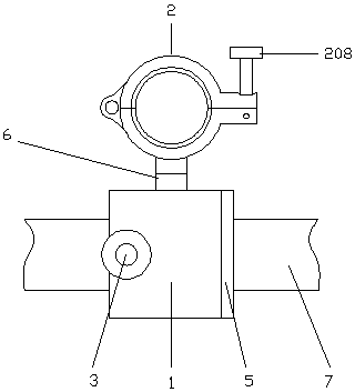
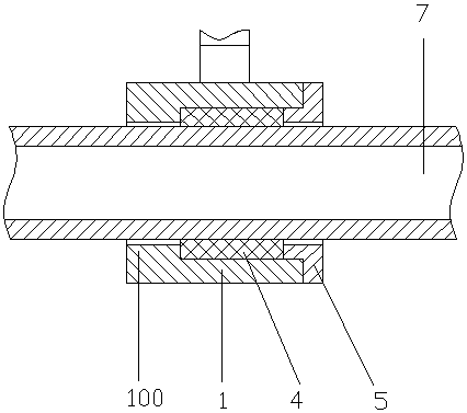
[0021] Such as figure 1 The wire locking and positioning assembly structure shown includes a sliding sleeve 1, a hoop 2 connected to the side of the sliding sleeve, and a locking mechanism 3 is provided in the sliding sleeve; figure 2 As shown, the inner center of the sliding sleeve is provided with a linear bearing 4, and the inner wall of one end of the sliding sleeve is provided with a limiting convex ring 100. The inner diameter of the limiting convex ring is larger than the inner diameter of the linear bearing and smaller than the outer diameter of the linear bearing. The other end of the sliding sleeve There is a bearing limit sleeve 5, and the threaded connection between the bearing limit sleeve and the sliding sleeve;

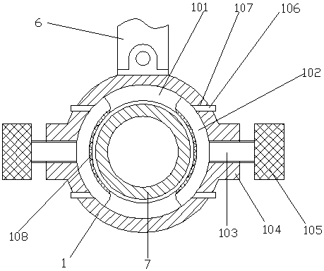
[0022] Such as image 3 As shown, the inner wall of the limiting convex ring 100 is provided with an annular groove 101, ...


PUM


Abstract

The invention relates to the technical field of live upright rod mounting, and discloses a wire locking and positioning assembly structure. The wire locking and positioning assembly structure comprises a sliding sleeve and a hoop connected with the side surface of the sliding sleeve; the sliding sleeve is internally provided with a lock mechanism; the hoop comprises an upper hook body and a lowerhook body; one end of the upper hook body and one end of the lower hook body are hinged; the other end of the upper hook body extends to form an upper lug; the other end of the lower hook body extendsto form a lower lug; outer ends of the lower lug and the upper lug are provided with grooves; the groove of the lower lug is internally provided with a stud; the stud and the lower lug are in rotating connection through a pin shaft; the outer end of the stud is provided with a screw sleeve; and the outer end of the screw sleeve is provided with a rotating handle. The wire locking and positioningassembly structure has the beneficial effects of convenient use and stable positioning.

Description

technical field [0001] The invention relates to the technical field of live pole installation, in particular to a wire locking and positioning component structure. Background technique [0002] Live pole operation refers to the operation of erecting a new high-voltage electric pole in a certain section of the high-voltage line. During this type of operation, two parallel high-voltage wires need to be pulled apart to increase the distance between the wires, providing for pole operation. Sufficient operating space ensures safe operation. At present, there are several operation methods for spreading the two conductors: the first is to use two electrified trolleys to carry out the work, and the electrified trolley stops at the two conductors, and the construction personnel pull the conductors apart through the electrified trolley; the second is Tie the insulating working ropes on the two conductors respectively, and two construction workers pull the conductors apart on the grou...

Claims


Application Information

Patent Timeline
Patent Type & Authority Applications(China)
IPC IPC(8): H02G1/02
CPCH02G1/02
Inventor 方雄伟张越夏耀春韩统方嘉伟徐辉颜明华钱宾刘利平童雄伟徐小峰
Owner STATE GRID ZHEJIANG ELECTRIC POWER CO LTD QUZHOU POWER SUPPLY CO
Why Eureka
Try Eureka