

gears for gear drives
A technology of gear transmission and planetary gear transmission, which is applied in gear transmission devices, transmission devices, hoisting devices, etc., and can solve problems such as limited structural space of torsion springs
- Summary
- Abstract
- Description
- Claims
- Application Information
AI Technical Summary
Problems solved by technology
Method used
Image

Examples
Embodiment Construction
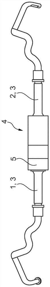
[0040] figure 1 Shown is an active roll stabilization device for a multi-train wheeled vehicle with a torsion bar 3 divided into two torsion bar parts 1 , 2 and an active actuating mechanism arranged between the two torsion bar parts 1 , 2 . device 4. This active roll stabilization device is arranged perpendicular to the longitudinal axis of the vehicle; its free end is connected to a wheel carrier, not shown in the drawing. The actuator 4 has a hollow cylindrical housing 5 in which an electric drive (not shown in the figure) and a planetary gear connected to the drive (also not shown in the figure) are accommodated. The housing 5 is connected to the torsion bar part 2 in a rotationally fixed manner. The output shaft (not shown) of the planetary gear is connected in a rotationally fixed manner to the torsion bar part 1 . When the actuator is actuated, the two torsion elements 1 , 2 rotate relative to each other and generate a torque.
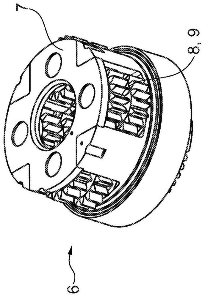
[0041] figure 2 A planetary gear st...
PUM
 Abstract
Description
Claims
Application Information