Eureka AIR delivers breakthrough ideas for toughest innovation challenges, trusted by R&D personnel around the world.

Parallel projection device

A parallel projection and projector technology, applied in the field of projection systems, can solve problems such as energy loss of projection light, limit application scenarios, and reduce screen size, and achieve the effect of improving light efficiency and space utilization.

Pending Publication Date: 2018-02-13
GUANGZHOU AIEN ELECTRONICS
View PDF0 Cites 0 Cited by
  • Summary
  • Abstract
  • Description
  • Claims
  • Application Information

AI Technical Summary

Problems solved by technology

The first type is suitable for large conference rooms, and the second type is suitable for small indoors, such as offices, conference rooms, etc., but more often, it is necessary to project images in a small space, but there is no guarantee that there is a space between the projector and the projection screen. Sufficient length can not guarantee the clarity of imaging
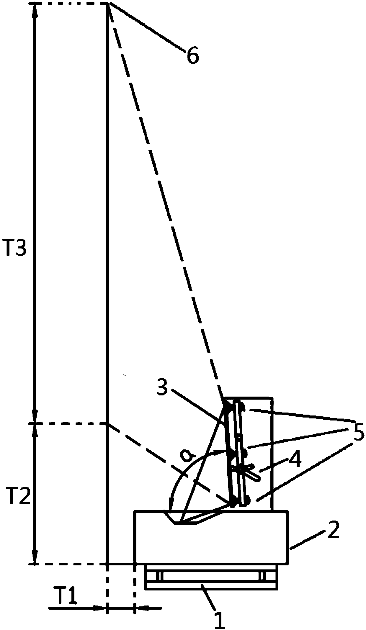
[0003] And existing fixed-focus projectors with a throw ratio less than 0.3 include wide-angle fixed-focus projectors with primary reflectors and have a short projection distance, but any change of the optical path due to the relationship of the fixed-focus lens must ensure that the distance between the image and the projector (T1 ), and the proportional relationship between the vertical distance (T2) from the bottom of the image to the extension line of the projector, otherwise it will cause distortion; and because the focal length is short, any small non-proportional change will expand the variable geometry of the distortion and cause the projected light energy Excessive loss
In order to reduce T1, it is generally adopted to add one or two flat reflectors vertically in front of the projector lens. The result of this method is that although the distance of T1 is reduced, the area of ​​the reflector is still the same. In actual use Among them, when the dimming glass is used as the rear projection imaging medium, the reflector can be seen after the dimming glass is electrified and becomes transparent, which is not beautiful and loses the meaning of using dimming glass
[0004] In addition, there is another way to add two flat mirrors obliquely in front of the projector lens, which reduces the distance of T1 and the area of ​​the mirrors, but produces too much distortion. Reduced size and excessive brightness loss limit application scenarios

Method used


Image

  • Parallel projection device
  • Parallel projection device
  • Parallel projection device

Examples


Embodiment Construction

[0023] The present invention will be described below in conjunction with the accompanying drawings, but not as a limitation to the present invention.

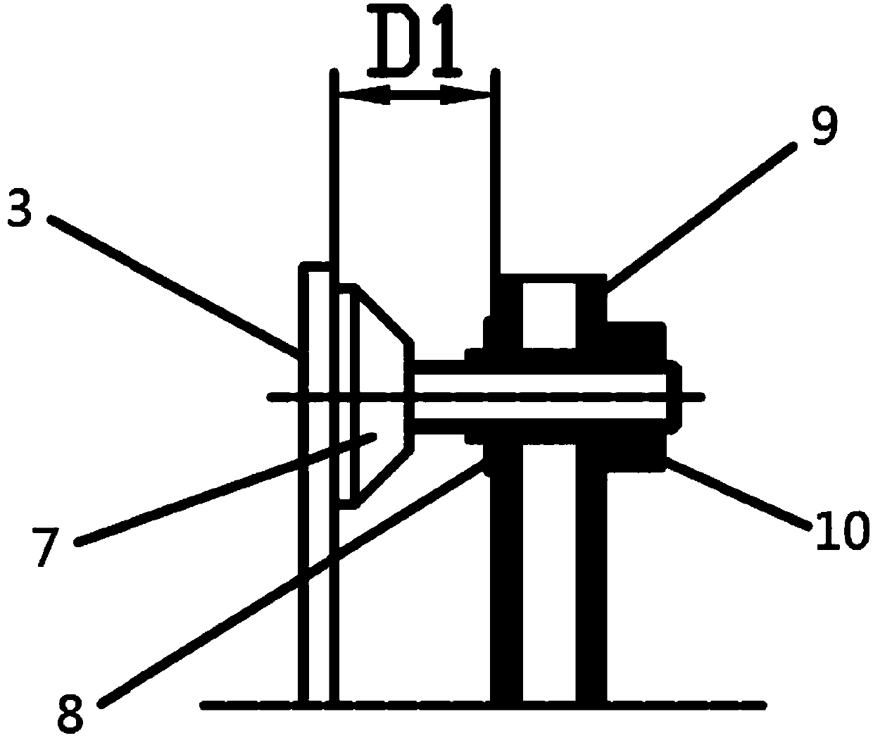
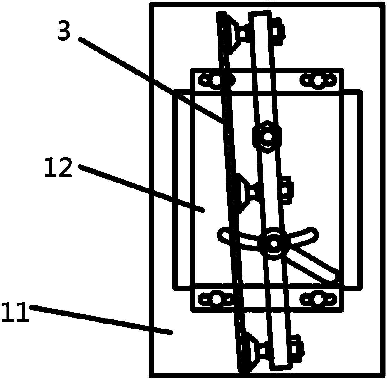
[0024] A parallel projection device, comprising a machine base 1, a projector 2, a side plate 11, a mirror 3, a mirror tilt adjustment mechanism 4, and a mirror arc adjustment mechanism 5, the projector 2 is located on the machine base 1, and the side The board 11 is erected on the projector 2, the reflector 3 is connected to the side plate 11 and forms an angle α with the horizontal plane of the projector 2, the mirror inclination adjustment mechanism 4 and the reflector arc adjustment mechanism 5 are arranged on the back of the reflector 3, and the reflector 3 The arc adjustment mechanism 5 includes a suction cup 7 , a retaining spring 8 , a mirror fixing frame 9 , and an adjustment nut 10 , and the mirror inclination adjustment mechanism 4 includes a rotating shaft 14 and an adjustment handle 13 .

[0025] Wherein, a mirror ...


PUM


Abstract

The invention discloses a parallel projection device. The device comprises an engine base, a projector, a side plate, a reflector, a reflector dip angle adjustment mechanism and a reflector arc adjustment mechanism, wherein the projector is arranged on the engine base, the side plate is erected on the projector, the reflector is connected with the side plate and forms an alpha angle with the horizontal plane of the projector, and the reflector dip angle adjustment mechanism and the reflector arc adjustment mechanism are arranged on the reverse side of the reflector. The parallel projection device is characterized in that the reflector arc adjustment mechanism comprises a sucking disk, a clamp spring, a reflector fixing frame and an adjusting screw nut, and the reflector dip angle adjustment mechanism comprises a revolving shaft and an adjusting handle. The parallel projection device is characterized by small throw ratio and clear imaging, and can meet use of some certain narrow and small spaces.

Description

technical field [0001] The invention relates to a projection system, in particular to a parallel projection device. Background technique [0002] The current projection system mainly includes two methods, one is to install on the ceiling and project the image on the projection screen or wall in a horizontal projection way; The first type is suitable for large conference rooms, and the second type is suitable for small indoors, such as offices, conference rooms, etc., but more often, it is necessary to project images in a small space, but there is no guarantee that there is a space between the projector and the projection screen. Sufficient length cannot guarantee the clarity of imaging. [0003] And existing fixed-focus projectors with a throw ratio less than 0.3 include wide-angle fixed-focus projectors with primary reflectors and have a short projection distance, but any change of the optical path due to the relationship of the fixed-focus lens must ensure that the distan...

Claims


Application Information

Patent Timeline
IPC IPC(8): G03B21/28G03B21/54
CPCG03B21/28G03B21/54
Inventor 腾文东
Owner GUANGZHOU AIEN ELECTRONICS
Why Eureka
Eureka Blog
Learn More