A cross-spinning strengthening forming method of titanium alloy thin-walled cylindrical parts

A forming method and technology for titanium alloys, applied in forming tools, metal processing equipment, manufacturing tools, etc., can solve the problems of low circumferential tensile strength and low axial tensile strength of titanium alloy thin-walled cylindrical parts, and achieve all directions. The effect of reducing anisotropy, increasing hoop strength, and weakening radial deformation texture strength

Active Publication Date: 2019-12-03
HARBIN INST OF TECH
View PDF7 Cites 0 Cited by
  • Summary
  • Abstract
  • Description
  • Claims
  • Application Information

AI Technical Summary

Problems solved by technology

[0004] The purpose of the present invention is to solve the obvious anisotropy of titanium alloy thin-walled cylindrical parts prepared by traditional titanium alloy spinning process, which causes the hoop tensile strength of titanium alloy thin-walled cylindrical parts to be lower than the axial tensile strength. In order to solve the problem of strength, a cross-spinning strengthening forming method for titanium alloy thin-walled cylindrical parts is provided

Method used


Image

  • A cross-spinning strengthening forming method of titanium alloy thin-walled cylindrical parts
  • A cross-spinning strengthening forming method of titanium alloy thin-walled cylindrical parts

Examples


specific Embodiment approach 1

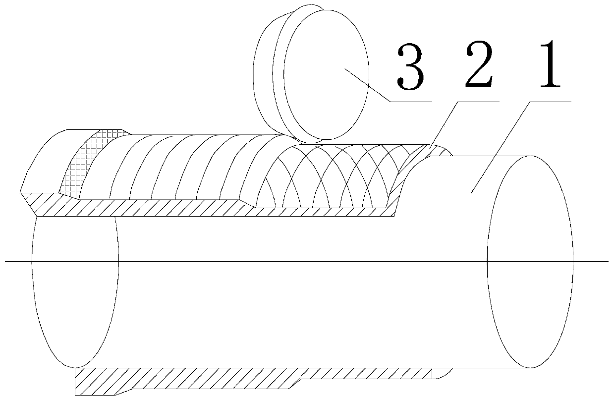
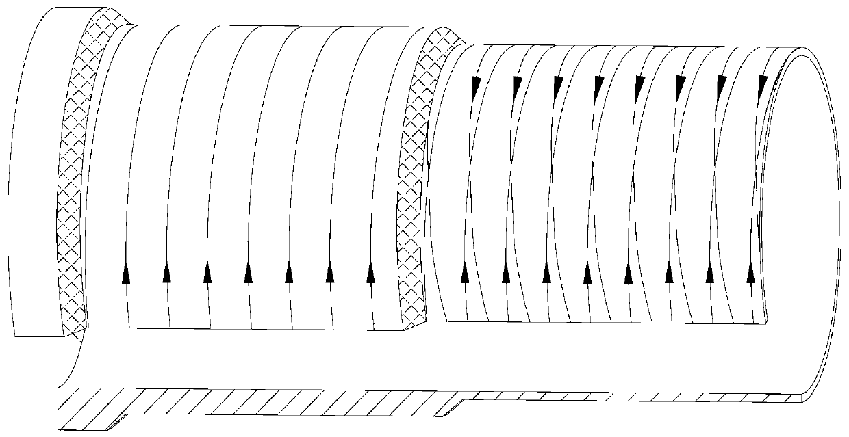
[0024] Specific implementation mode one: combine figure 1 and figure 2 Describe this embodiment, the cross-spinning strengthened forming method of titanium alloy thin-walled cylindrical part in this embodiment, it is characterized in that: this method is carried out according to the following steps:

[0025] Step 1: Put the titanium alloy billet on the mandrel of the spinning machine and fix it, preheat the mandrel of the spinning machine and the titanium alloy billet, and spray evenly on the outer surface of the mandrel of the spinning machine and the outer surface of the titanium alloy billet Lubricant; the mandrel of the spinning machine is preheated to 150-200°C, and the titanium alloy blank is preheated to 350-400°C;

[0026] Step 2: preheat the mandrel and blank of the spinning machine to 650-850°C, and preheat the spinning wheel of the spinning machine to 100-150°C;

[0027] Step 3: Start the spinning machine for strong spinning;

[0028] Step 4: Change the rotation...

specific Embodiment approach 2

[0034] Embodiment 2: The difference between this embodiment and Embodiment 1 is that the material of the steel used for the wheel of the spinning machine and the mandrel of the press in Step 1 is 4Cr5MoSiV1. Other steps and parameters are the same as those in the first embodiment.

specific Embodiment approach 3

[0035] Embodiment 3: The difference between this embodiment and Embodiment 1 or 2 is that when the titanium alloy blank is placed on the mandrel of the spinning machine in step 1, there is a transition between the titanium alloy blank and the mandrel of the press Cooperate. Other steps and parameters are the same as those in Embodiment 1 or 2.


PUM


Abstract

The invention discloses a cross spinning intensified molding method for a titanium alloy thin-wall barrel-shaped part and relates to a barrel-shaped part molding method. The cross spinning intensifiedmolding method aims at solving the problem that a titanium alloy thin-wall barrel-shaped part prepared through a traditional titanium alloy spinning process is likely to generate obvious anisotropism, so that the circumferential tensile strength of the titanium alloy thin-wall barrel-shaped part is lower than the axial tensile strength. The method comprises the steps of 1, fixing a billet material, preheating a central spindle and the billet material, and spraying a lubricating agent; 2, preheating the central spindle, a rotary wheel and the billet material to the spinning temperature; 3, conducting powerful spinning; 4, changing the rotation direction of the central spindle of a spinning machine, and conducting power spinning of the next pass; and 5, repeating step 4 till the titanium alloy thin-wall barrel-shaped part of the target size is obtained. Anisotropism of the titanium alloy thin-wall barrel-shaped part produced through the method is obviously lowered; the titanium alloy thin-wall barrel-shaped part produced through the method is uniform in microstructure distribution, and the grain size is smaller; and the cross spinning intensified molding method is applicable to molding of the thin-wall barrel-shaped part.

Description

technical field [0001] The invention relates to a method for forming a cylindrical part. Background technique [0002] With the increasingly complex service environment of thin-walled rotary components in the aerospace field, thin-walled rotary components represented by modern rocket and missile engine shells are often subjected to various complex conditions such as high temperature, high pressure, high speed and chemical atmosphere during service. Due to the effect of load, the requirements for the performance of thin-walled rotary components such as strength, toughness, heat resistance, corrosion resistance, fatigue, etc. are constantly increasing, especially for titanium alloy thin-walled cylindrical parts that Cylindrical shell components have high dimensional accuracy, and at the same time require components to have good organizational properties and stable mechanical properties to meet the use requirements of components under increasingly complex conditions. Therefore...

Claims


Application Information

Patent Timeline
Patent Type & Authority Patents(China)
IPC IPC(8): B21D22/16B21D37/16B21D37/18B21D51/10
CPCB21D22/16B21D37/16B21D37/18B21D51/10
Inventor 徐文臣单德彬万星杰吴鹤赵小凯
Owner HARBIN INST OF TECH
Why Eureka
Try Eureka