Efficiency improving and cost reducing method for pipe end expansion and special expansion mold

A mold and pipe end technology, which is applied in the field of seamless steel pipe end sizing, can solve the problems of many specifications of pipe end sizing machine expansion molds, easy damage of clamps, frequent replacement, etc., to achieve outstanding substantive features and production efficiency and the effect of cost improvement and cost reduction

Inactive Publication Date: 2018-02-16
烟台鲁宝钢管有限责任公司
View PDF8 Cites 4 Cited by
  • Summary
  • Abstract
  • Description
  • Claims
  • Application Information

AI Technical Summary

Problems solved by technology

[0005] The invention mainly solves the problems of the existing pipe end sizing machine, such as many specifications of expansion molds, frequent replacement, easy damage of the clamps to the steel pipe and the application and cleaning of lubricants, etc.

Method used


Image

  • Efficiency improving and cost reducing method for pipe end expansion and special expansion mold
  • Efficiency improving and cost reducing method for pipe end expansion and special expansion mold
  • Efficiency improving and cost reducing method for pipe end expansion and special expansion mold

Examples


Embodiment 1

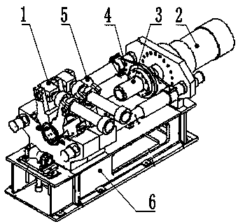
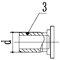
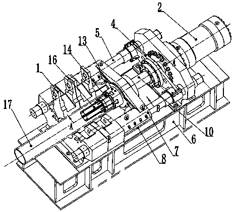
[0025] Example 1, see image 3 , 4 , 5, 6, taking the tapered push rod of the special expanding die with 6 slopes as an example;

[0026] Select a suitable supporting flange 13, install the shaft sleeve 12 in the inner hole of the supporting flange 13, install the connecting rod 10 in the shaft sleeve 12, and install the connecting rod 10 in the inner shaft of the shaft sleeve 12 installed in the center hole of the supporting flange 13 The right end of the connecting rod 10 is connected to the sliding seat 4, and the left end is connected to the tapered push rod 11 through threads; the tapered push rod 11 is provided with 6 inclined surfaces evenly distributed, and one is installed on each inclined surface to cooperate with it. The fan-shaped mold block 14, the corresponding slope of the fan-shaped mold block 14 keeps in contact with the slope of the tapered push rod 11 by the guide key 15, and the right end surface of the fan-shaped mold block 14 is connected with the T-shap...

Embodiment 2

[0033] Embodiment 2, referring to 7, is the same as embodiment 1, taking the tapered push rod of the special expanding die with 5 slopes as an example; the tapered push rod 11 of the expanding die has 5 slopes, and one is installed on each slope Sector mold block 14.

[0034] For the supporting special expansion die of the above-mentioned embodiment 2, the inner diameter of the expansion steel pipe is φ230-φ330mm; within this range, two kinds of expansion die combinations of specifications are set up, and 5 kinds of sector shapes are equipped with a difference of 20mm in nominal external diameter. Mold block group; when changing specifications, only the fan-shaped mold block 14 can be replaced.

Embodiment 3

[0035] Example 3, see Figure 8 , with embodiment 1, take the tapered push rod of special-purpose expanding die to have 4 slopes as example;

[0036] The matching mold of the above-mentioned embodiment 3 has an inner diameter of the expanded diameter steel pipe of φ140-φ230mm; within this range, 3 kinds of specifications of the expanded diameter mold combination are set; when changing the specifications, only the fan-shaped mold block 14 can be replaced.

[0037] The invention discloses a method for increasing the efficiency and reducing the cost of pipe end diameter expansion and a special diameter expansion mold. According to the inner diameter of the steel pipe, a suitable diameter expansion mold combination and a fan-shaped mold block group with matching sizes are selected, and they are installed on the supporting and fixing device. , to form a complete supporting mold for expanding diameter, and then install the supporting mold on the pipe end sizing machine, connect the ri...


PUM


Abstract

The invention discloses an efficiency improving and cost reducing method for pipe end expansion and a special expansion mold. Through the mated expansion mold, the method can change pipe end expandersof axially pressing the expansion mold into the pipe ends of clamped steel pipes through pressure for expansion as pipe end expanders for pipe end expansion through radial extension by multiple fan-shaped modules under the effects of inclined surfaces; and due to change of the expansion mode, the specification, the number and the replacement times of the expansion mold can be reduced, and three procedures of clamping, coating and lubricating agent cleaning in pipe end expansion of the steel pipes are saved, so that the production efficiency and the cost in pipe end expansion are greatly improved. In the mated mold, the mold with one specification can be suitable for pipe end expansion of the steel pipes in a certain inner diameter range without needing clamping of the steel pipes and lubrication of a working surface of the mold.

Description

Technical field: [0001] The present invention relates to the technical field of pipe end sizing of seamless steel pipes, and specifically relates to a method for pipe end diameter expansion to improve efficiency and reduce costs and a special diameter expansion die; The improvement of the diameter expansion method of the pipe end sizing machine to press into the end of the clamped steel pipe to expand the diameter is to achieve the purpose of improving production efficiency and reducing costs during diameter expansion. Background technique: [0002] At present, the known pipe end sizing machine is composed of a steel pipe clamp 1, a main hydraulic cylinder 2, an expanding or shrinking die 3, a sliding seat 4, a guide rod 5 and a support 6. The working process is: apply lubricant to the working surface of the mold, the steel pipe is sent to the pipe end sizing machine by the conveying roller table, after the pipe end reaches the sizing position, the steel pipe is clamped by t...

Claims


Application Information

Patent Timeline
Patent Type & Authority Applications(China)
IPC IPC(8): B21D37/10B21D41/02
CPCB21D37/10B21D41/028
Inventor 迟黎明张英江
Owner 烟台鲁宝钢管有限责任公司
Why Eureka
Try Eureka