Multifunctional snow throwing device

A snow throwing device and multi-functional technology, which can be used in snow surface cleaning, construction, cleaning methods, etc., can solve the problems of waste of manpower and material resources, high price, short snow throwing distance, etc. fast effect

Pending Publication Date: 2018-02-16
WEIHAI GUANGTAI AIRPORT EQUIP CO LTD
View PDF17 Cites 2 Cited by
  • Summary
  • Abstract
  • Description
  • Claims
  • Application Information

AI Technical Summary

Problems solved by technology

Road snow removal operations often only push the snow to the side of the road. If they are not thrown out of the roadside or transported away in time, it will form a traffic bottleneck and cause snow obstruction; if the snow is not removed in time at the airport, it will affect Flights affect normal production and life
[0003] At present, there are many domestic manufacturers of snow throwing machines. CN201420712443.9 discloses a cleaning snow throwing machine, CN201220080100.6 discloses a snow throwing machine, etc. The substantial disadvantages of these snow throwing machines are: low snow throwing efficiency, The snow throwing distance is short, only suitable for highways and municipal areas; not suitable for airports, and the snow throwing machines used in domestic airports have to rely on imports, which are expensive and not timely after-sales, and cannot meet the requirements of consumers
Especially for areas with very heavy snowfall in winter in Northeast China and Xinjiang, when the snowfall exceeds 10mm, the snowfall on the general runway will reach 1500-2000 tons, and the snow removal effect is very slow when using existing snow throwing equipment to clean up the snow , in order to increase the speed of snow removal, the snow blower and the three-in-one snow remover can only be used in formation, so manpower and material resources are greatly wasted

Method used


Image

  • Multifunctional snow throwing device
  • Multifunctional snow throwing device
  • Multifunctional snow throwing device

Examples


Embodiment Construction

[0024] The present invention will be described below in conjunction with the accompanying drawings and embodiments.

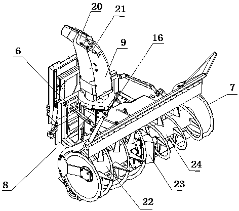
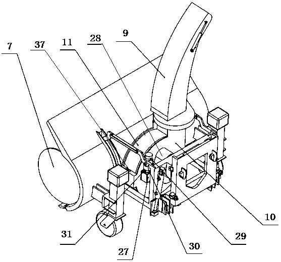
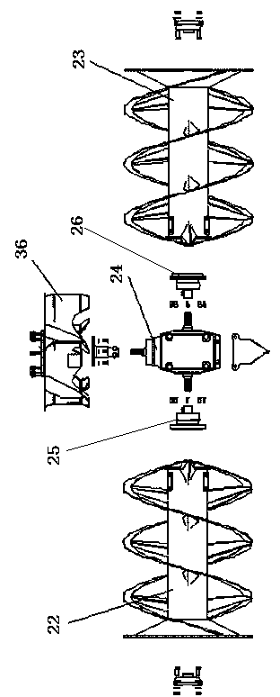
[0025]As shown in the accompanying drawings, a multifunctional snow throwing device includes a frame 6, a cage assembly 7, a thrower 8, and a snow guide cover 9, and the frame is provided with the cage assembly and the thrower. The upper end of the thrower is provided with a snow guide cover, and the thrower 8 is composed of an ejector 36, a high throw shell 10, a rotating housing 11, a connecting block 43, a front rotating housing turning device and a rear rotating housing turning device, Described high throw shell 10 is made up of front fixed plate 13, rear fixed plate 14 and connecting flange 15, and described front fixed plate 13 and rear fixed plate 14 are arranged in parallel, and described front fixed plate and rear fixed plate are respectively connected with machine The frame is fixedly connected, the upper ends of the front fixed plate 13 and the rear ...


PUM


Abstract

The invention discloses a multifunctional snow throwing device which comprises a rack, a cage component, a thrower and a snow guide cover and is characterized in that the thrower is composed of an ejector, a highly throwing casing, a rotating shell, a front rotating shell slewing gear and a rear rotating shell slewing gear; the highly throwing casing is composed of a front fixed plate, a rear fixed plate and a connecting flange; the front fixed plate and the rear fixed plate are arranged in parallel; the front fixed plate and the rear fixed plate are fixedly connected with the rack respectively; the upper ends of the front fixed plate and the rear fixed plate are fixedly connected with the connecting flange; a center hole of the front fixed plate communicates with an ejector port of the cage component; the upper end of the connecting flange is connected with the snow guide cover; the rotating shell is positioned between the front fixed plate and the rear fixed plate; and the ejector isarranged in the rotating shell. The multifunctional snow throwing device has the advantages of simple structure, convenient use, low equipment cost, high snow removal speed, thorough snow removal, high working efficiency and the like.

Description

technical field [0001] The invention relates to the technical field of snow removal equipment, in particular to a multifunctional snow throwing device. Background technique [0002] The main working objects of the snow blower are natural snowfall and accumulated snow, which are widely used in road opening operations, widening snow removal operations, snow loading operations and disaster relief work. Its special effect is often irreplaceable by other snow removal machinery, including the most widely used scraping machinery. Road snow removal operations often only push the snow to the side of the road. If they are not thrown out of the roadside or transported away in time, it will form a traffic bottleneck and cause snow obstruction; if the snow is not removed in time at the airport, it will affect Flights have an impact on normal production and life. [0003] At present, there are many domestic manufacturers of snow throwing machines. CN201420712443.9 discloses a cleaning s...

Claims


Application Information

Patent Timeline
Patent Type & Authority Applications(China)
IPC IPC(8): E01H5/07
CPCE01H5/07
Inventor 唐明磊戚洪涛丛晓杰都奎江李佳兴熊伟
Owner WEIHAI GUANGTAI AIRPORT EQUIP CO LTD
Why Eureka
Try Eureka