Cross laser image roadbed surface settlement monitoring method and system

A technology for subgrade surface and settlement monitoring, which is applied in the field of image processing, can solve problems such as spot center positioning interference, enlarge the laser interference area, and difficulty in perpendicularity, etc., and achieve the effect of short time consumption and high calculation accuracy

Inactive Publication Date: 2018-02-16
LANZHOU JIAOTONG UNIV
View PDF4 Cites 9 Cited by
  • Summary
  • Abstract
  • Description
  • Claims
  • Application Information

AI Technical Summary

Problems solved by technology

Most monitoring systems use point structured light for measurement, and the point light source emitted by the reference point is far away from the receiving target surface of the monitoring point. Due to the diffraction effect, the light spot on the receiving target surface is a multi-level diffraction ring with a central bright spot. The appearance of ring stripes expands the interference area of ​​the laser and enhances the interference effect of the laser on the camera; and it is difficult to ensure that the point laser is perpendicular to the receiving target surface during on-site monitoring, so when the point laser is projected onto the receiving target surface, due to reflection and refraction, There is not only one light spot on the receiving target surface, which greatly interferes with the positioning of the center of the light spot

Method used


Image

  • Cross laser image roadbed surface settlement monitoring method and system
  • Cross laser image roadbed surface settlement monitoring method and system
  • Cross laser image roadbed surface settlement monitoring method and system

Examples


Embodiment 1

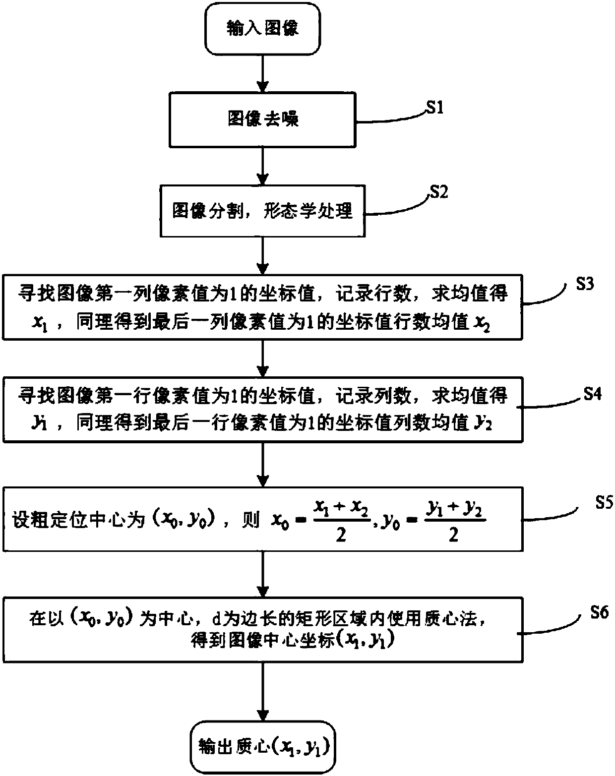
[0029] See figure 1 According to the embodiment of the present invention, the cross-laser image-type subgrade surface settlement monitoring method specifically includes the following steps:

[0030] S1. Image denoising: collect laser images through an image acquisition device, and perform denoising processing on the collected laser images through an adaptive median filter algorithm;

[0031] S2. Image threshold segmentation and morphological processing: identify and analyze the target in the image, and use the maximum inter-class variance method to determine the threshold range to separate the target from the laser image to obtain a binarized laser image; for the binarized laser image Perform morphological opening and closing operations;

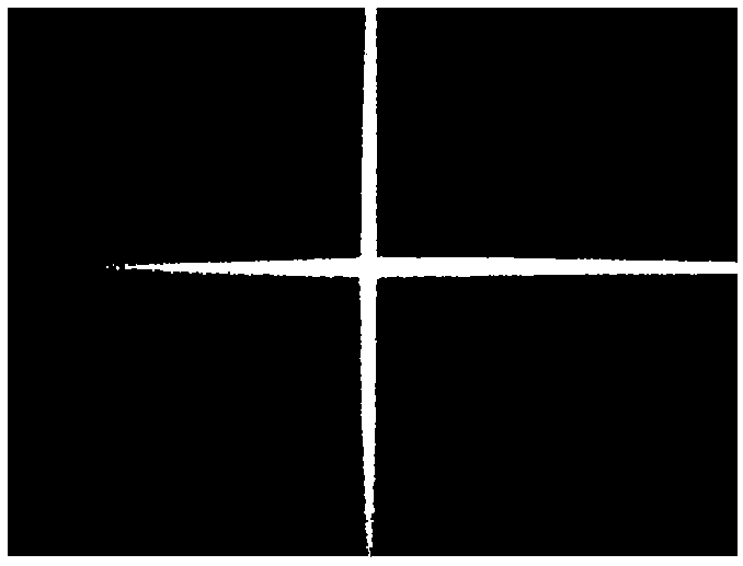
[0032] S3. Coarse positioning of the abscissa of the cross spot: find the coordinate value of the first column of the laser image with a pixel value of 1, record the number of rows, and calculate the average value as x1, and similarly obtai...

Embodiment 2

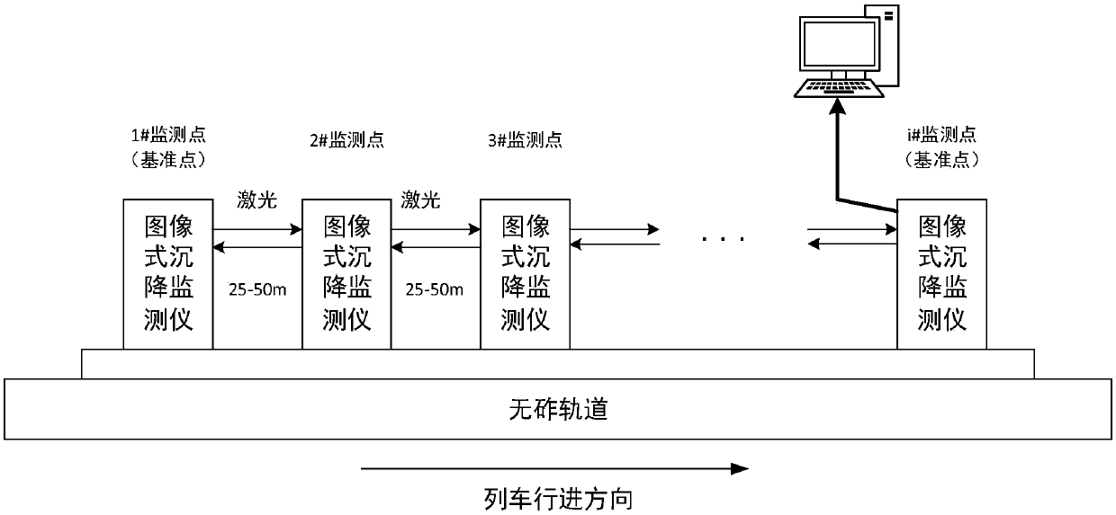
[0047] The present invention also provides a cross-laser image-type roadbed surface settlement monitoring system, which is applied on the roadbed surface. The system includes a first reference point, a tail reference point, and i monitoring points (also called transfer points), where i is greater than 1 The first reference point and the tail reference point are respectively located at the two ends of the roadbed surface; the i monitoring points are arranged along the direction of the first reference point towards the tail reference point, and are arranged according to the requirements of the monitoring section, and the distance between them is generally Between 25-50m.

[0048] The first reference point, the tail reference point, and the i monitoring points are all equipped with image settlement monitors. The image-type subsidence monitor includes a cross laser, a receiving target surface, an image acquisition device and a processing unit; the cross laser is used to emit laser...


PUM


Abstract

The present invention relates to the field of image processing technology, especially to a cross laser image roadbed surface settlement monitoring method. The method comprises the steps of: image denoising; image threshold segmentation and morphological processing; coarse positioning of horizontal ordinates of a cross light spot; coarse positioning of longitudinal coordinates of the cross light spot; and obtaining of a coarse positioning center, wherein the coarse positioning center is taken as a center to obtain center coordinates of the image through adoption of a gray centroid method. According to the monitoring method, image denoising, image threshold segmentation and morphological processing are combined to obtain a cross light spot having a smooth edge, and a two-step positioning algorithm with combination of coarse positioning of a cross point of intersection and the local gray centroid method is provided to obtain the accurate positioning center of the image. The algorithm provided by the invention has higher calculation precision and is shorter in time compared to a method of positioning of an elliptic spot through adoption of a gray centroid method.

Description

technical field [0001] The invention relates to the technical field of image processing, in particular to an image-type subgrade surface settlement monitoring method and monitoring system of a cross laser. Background technique [0002] The observation of the leveling line of the ballastless track subgrade is based on the second-class leveling accuracy requirements to form a combined leveling line, and the accuracy of the leveling measurement of the subgrade settlement observation is 1.0mm. However, traditional monitoring methods such as observation piles, settlement plates, and settlement cups cannot be automatically and continuously monitored. [0003] Image center positioning technology is an important part of the measurement system, which directly affects the measurement accuracy. Most monitoring systems use point structured light for measurement, and the point light source emitted by the reference point is far away from the receiving target surface of the monitoring poi...

Claims


Application Information

Patent Timeline
Patent Type & Authority Applications(China)
IPC IPC(8): G06T7/00G06T7/11G06T7/136G06T7/155G06T7/66E01C23/01
CPCE01C23/01G06T7/0004G06T2207/30132G06T7/11G06T7/136G06T7/155G06T7/66
Inventor 闵永智郭薇党建武张振海林俊亭张雁鹏张鑫
Owner LANZHOU JIAOTONG UNIV
Why Eureka
Try Eureka