OTG power supply and wireless charging compatible circuit, related method, and terminal device

A technology of wireless charging and compatible circuits, which is applied to battery circuit devices, circuit devices, current collectors, etc., and can solve problems such as inability to use OTG functions

Active Publication Date: 2018-02-16
MEIZU TECH CO LTD
View PDF7 Cites 9 Cited by
  • Summary
  • Abstract
  • Description
  • Claims
  • Application Information

AI Technical Summary

Problems solved by technology

[0004] Embodiments of the present invention provide an OTG power supply and wireless charging compatible circuit, a related method, and a terminal device to solve the problem that the existing terminal device cannot use the OTG function while performing wireless charging

Method used


Image

  • OTG power supply and wireless charging compatible circuit, related method, and terminal device
  • OTG power supply and wireless charging compatible circuit, related method, and terminal device
  • OTG power supply and wireless charging compatible circuit, related method, and terminal device

Examples


Embodiment 1

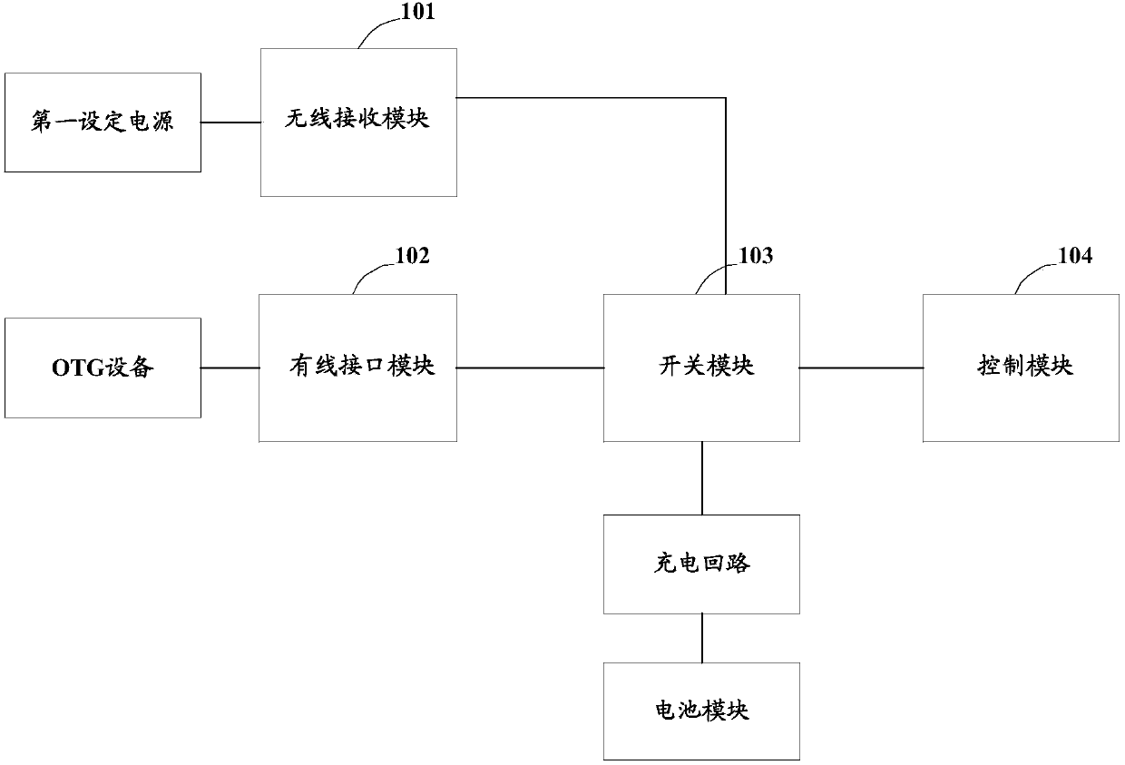
[0048] Embodiment 1 of the present invention provides an OTG power supply and wireless charging compatible circuit, specifically, as figure 1 As shown, it is a schematic structural diagram of the OTG power supply and wireless charging compatible circuit described in Embodiment 1 of the present invention, which may include a wireless receiving module 101, a wired interface module 102, a switch module 103, and a control module 104, wherein:

[0049] The control module 104 is configured to send a first switch control signal to the switch module 103 if it is determined that the wireless receiving module 101 is connected to a first set power supply and the wired interface module 102 is connected to an OTG device;

[0050] The switch module 103 is configured to respond to the first switch control signal, conduct the electrical connection between the wireless receiving module 101 and the charging circuit, and conduct the electrical connection between the wireless receiving module 101 ...

Embodiment 2

[0087] Based on the same inventive concept, Embodiment 2 of the present invention provides an OTG power supply and wireless charging compatible method, which is applied to a terminal device, and the terminal device may include a wireless receiving module, a wired interface module and a switch module. Specifically, as Figure 5 As shown, it is a flow chart of the steps of the OTG power supply and wireless charging compatible method described in Embodiment 2 of the present invention, and the method may include:

[0088] Step 501: If it is determined that the wireless receiving module is connected to the first set power supply and the wired interface module is connected to the OTG device;

[0089] Step 502: Control the switch module so that the wireless receiving module is electrically connected to the charging circuit and the wired interface module respectively, and the wired interface module is disconnected from the charging circuit;

[0090] Step 503: and, control the wireles...


PUM


Abstract

The invention relates to the technical field of charging, in particular to an OTG power supply and wireless charging compatible circuit, a related method and a terminal device. A switch module is arranged so that when the terminal device is determined to perform wireless charging, an OTG device is connected at the same, the switch module is controlled to enable a wireless reception module to be electrically connected to a charging circuit of a battery module and a wired interface module and to enable the wired interface module to be disconnected with the charging circuit, thereby enabling thewireless reception module to supply electric energy to the charging circuit and the OTG device at the same time. Therefore, wireless charging and the OTG function of the terminal device can be performed at the same time.

Description

technical field [0001] The invention relates to the technical field of charging, in particular to an OTG power supply and wireless charging compatible circuit, a related method, and a terminal device. Background technique [0002] OTG is the abbreviation of On-The-Go, which is mainly used in the connection and data transmission between various devices without a Host. For example, based on OTG technology, a digital camera can be directly connected to a printer through the USB (Universal Serial Bus, Universal Serial Bus) interfaces of two devices to print out the photos taken; The data is sent to the mobile hard disk, so that it is no longer necessary to carry an expensive digital camera memory card or a laptop used as a Host when working in the field. In addition, based on OTG technology, it is also possible to expand the USB interface accessories of the smart terminal to enrich the functions of the smart terminal; for example, to expand the remote control accessories, the s...

Claims


Application Information

Patent Timeline
Patent Type & Authority Applications(China)
IPC IPC(8): H02J7/00H02J50/00
CPCH02J7/025H02J7/0068H02J50/00
Inventor 易鹏程
Owner MEIZU TECH CO LTD
Why Eureka
Try Eureka