Suction nozzle for a vacuum cleaner

A technology of vacuum cleaners and sensors, applied in the direction of vacuum cleaners, suction nozzles, applications, etc.

Active Publication Date: 2018-02-16
VORWERK & CO INTERHOLDING GMBH
View PDF6 Cites 7 Cited by
  • Summary
  • Abstract
  • Description
  • Claims
  • Application Information

AI Technical Summary

Problems solved by technology

[0003] Although the aforementioned suction nozzle is known in the prior art, this suction nozzle can only detect the aspirated material in front of the suction edge arranged on the suction nozzle at the front based on the usual forward movement

Method used


Image

  • Suction nozzle for a vacuum cleaner
  • Suction nozzle for a vacuum cleaner
  • Suction nozzle for a vacuum cleaner

Examples


Embodiment Construction

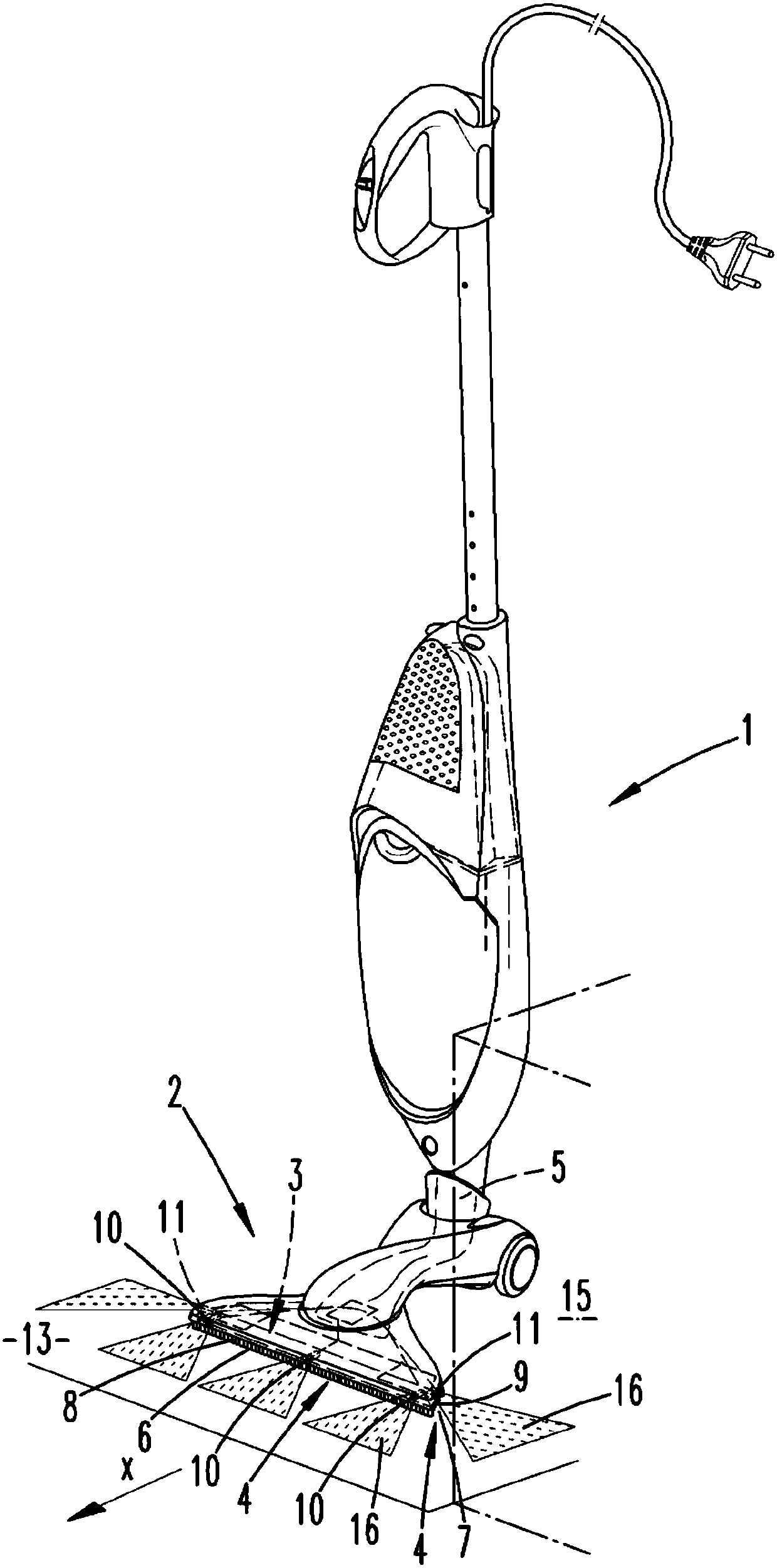
[0025] exist figure 1 The vacuum cleaner 1 shown in is a conventional hand-held floor vacuum cleaner with a suction nozzle 2 according to the invention. The suction nozzle 2 has a suction opening 3 , the suction air flow outlet 5 of which is fluidically connected to the fan of the vacuum cleaner 1 via a corresponding channel connection. Suction material sucked in through the suction opening 3 of the suction nozzle 2 thus passes through the suction air flow outlet 5 into the filter chamber of the vacuum cleaner 1 , which is provided in a conventional manner, for example with a dust filter bag.

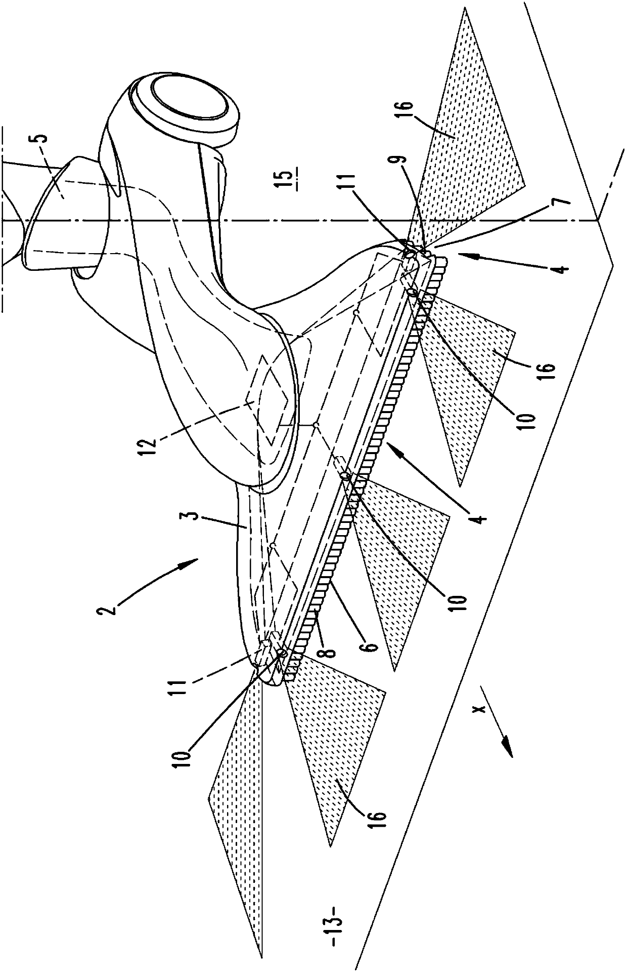
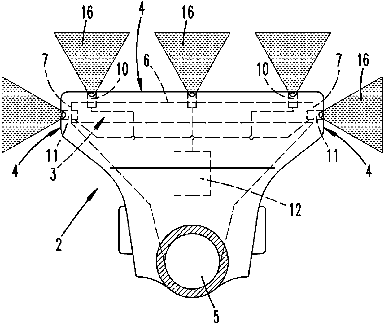
[0026] Such as figure 2 As shown in detail, the suction nozzle 2 has a suction opening 3 , the suction edge 4 of which defines the partial area of ​​the surface 13 to be cleaned to which the negative pressure is applied. The suction edge 4 has a plurality of suction edge sections 6 , 7 , of which a first suction edge section 6 is oriented substantially perpendicularly to the general ...


PUM


Abstract

The invention relates to a suction nozzle (2) for a vacuum cleaner (1) for sucking up items to be vacuumed from a surface (13) to be cleaned by means of a vacuum air stream, wherein the suction nozzle(2) has: a suction mouth (3) which can be arranged adjacently to the surface (13) to be cleaned and which comprises a suction edge (4) that delimits a sub-surface exposed to the vacuum air stream; avacuum air stream extraction opening (5); and a delimiting means (8, 9) associated with the suction edge (4), which means can be controlled according to a detection result of a sensor. In order to produce a suction nozzle (2) whose delimiting means (8, 9) can be moved variably if other events occur, the sensor is an obstacle sensor (10, 11) for detecting a substantially stationary obstacle (15) located in front of the suction nozzle (2), in particular a wall or piece of furniture, wherein the obstacle sensor (10, 11) is configured to detect obstacles (15) that are disposed outside the portionof the surface (13) over which the suction nozzle (2) projects and, in relation to an arrangement of the suction nozzle (2) during typical cleaning operation, that protrude beyond a suction edge planethat has the suction edge (4). The invention further relates to a vacuum cleaner (1) with such a suction nozzle (2) and a method for sucking up items to be vacuumed by means of a suction nozzle (2).

Description

technical field [0001] The invention relates to a suction nozzle for a vacuum cleaner for suctioning suction from a surface to be cleaned by means of a suction air flow, wherein the suction nozzle has a suction opening which can be arranged adjacent to the surface to be cleaned, The suction opening has a suction edge delimiting a partial surface to which the suction air flow is applied and a suction air flow outlet, and the suction nozzle also has a restriction associated with the suction edge, the restriction Can be controlled according to the detection result of the sensor. Background technique [0002] Suction nozzles of the above-mentioned type are sufficiently known in the prior art. Document WO 2007 / 074035 A1 discloses, for example, a suction nozzle for sucking in aspiration, which has a vertically displaceable restriction at the front in the normal feed direction. The suction nozzle has a sensor directed at the surface to be cleaned for detecting the dimensional pro...

Claims


Application Information

Patent Timeline
Patent Type & Authority Applications(China)
IPC IPC(8): A47L9/02A47L9/28A47L9/06
CPCA47L9/02A47L9/06A47L9/0633A47L9/28A47L5/28A47L9/2805A47L9/2842
Inventor M.科内利森
Owner VORWERK & CO INTERHOLDING GMBH
Why Eureka
Try Eureka