Power loss dysfunction characterization

A power loss and failure technology, applied in surveying, wellbore/well components, directional drilling, etc., can solve problems such as inaccurate timing of independent sensors, difficulty in detecting or predicting downhole drilling failures, affecting variable timing drift of sensors, etc.

Active Publication Date: 2018-02-16
CONOCOPHILLIPS CO
View PDF4 Cites 0 Cited by
  • Summary
  • Abstract
  • Description
  • Claims
  • Application Information

AI Technical Summary

Problems solved by technology

However, each sensor may have its own internal clock, or data from many sensors may be acquired and recorded relative to multiple clocks that are not synchronized
This asynchronous nature of timing information creates problems when merging and processing data from different sensors
In addition, sensor timing is known to be sometimes affected by various environmental factors that cause variable timing drift that can affect various sensors differently
A number of factors can make the timing of individual sensors inaccurate, and the sensors then need to be corrected or adjusted so that the data can be properly assimilated with all sensor information consistent in time in order to incorporate the dynamic state of the well being drilled. Accurately inform drilling operation centers
[0007] Downhole drilling failures can cause serious operational problems that are difficult to detect or predict

Method used


Image

  • Power loss dysfunction characterization
  • Power loss dysfunction characterization
  • Power loss dysfunction characterization

Examples


Embodiment Construction

[0020] Turning now to the specific description of the preferred arrangements of the invention, it should be understood that the features and concepts of the invention may be embodied in other arrangements and that the scope of the invention is not limited to the described or illustrated embodiments. It is intended that the scope of the present invention be limited only by the scope of the following claims.

[0021] The following examples of certain embodiments of the invention are given. Each example is provided by way of illustration of the invention, which is one of many embodiments of the invention, and the following examples should not be construed to limit or define the scope of the invention.

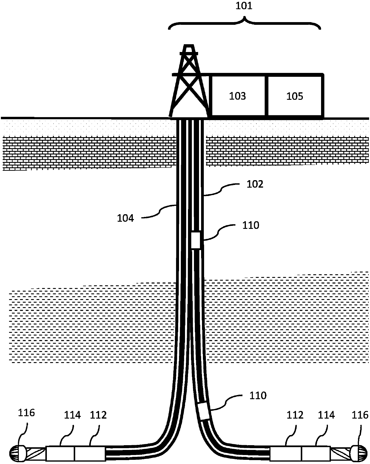
[0022] figure 1 An example of a formation having a first wellbore and a second wellbore according to various embodiments of the present disclosure is shown. The various embodiments disclosed herein are used in applications such as figure 1 The illustrated drilling environment i...


PUM


Abstract

The invention relates to a method, system and apparatus for determining real-time drilling operations dysfunctions by measuring the power-loss of signal propagation associated with a drill string in awellbore. The invention comprises acquiring a first time series from a mid-string drilling sub sensor associated with a drill string in a wellbore and acquiring a second time series from a sensor associated with the drill string wherein the sensor is on or near a drill rig on the surface of the earth. The process further comprises determining the geometry of the wellbore and determining model parameters alpha and beta for characterizing a wellbore using the first time series, the second time series and the geometry of the wellbore by deriving a power loss of signal propagation. The model parameters may then be used for drilling a subsequent well using surface sensor acquired data to detect drilling dysfunctions.

Description

[0001] Statement Regarding Federally Sponsored Research or Development [0002] none. technical field [0003] The present invention generally relates to detecting and mitigating faults in drilling. More specifically but not limiting, embodiments of the present invention include predicting real-time failures at any location on the drill string by modeling the wellbore environment, thereby enabling recovery of signal energy from the drill string under operating conditions, which allows Detect and mitigate downhole drilling failures, which are detected by sensors on the surface. Background technique [0004] Hydrocarbon reserves are developed by drilling operations using a drill bit associated with a drill string that is rotated from the surface or using a downhole motor, or both using a downhole motor and rotating the drill string from the surface. The bottom hole assembly (BHA) at the end of the drill string may include components such as drill collars, centralizers, drill...

Claims


Application Information

Patent Timeline
IPC IPC(8): E21B47/12E21B7/04E21B47/16G01V3/38
CPCE21B44/04
Inventor H·M·克利P·D·安诺S·C·拉姆齐
Owner CONOCOPHILLIPS CO
Why Eureka
Try Eureka