Spacewalk machine with movable handle

A spacewalking machine and movable handle technology, applied in sports accessories, training equipment for adjusting coordination, training equipment for adjusting cardiovascular system, etc., can solve problems such as lack of exercise for arms, short service life, poor experience, etc. Achieve good experience and long service life

Inactive Publication Date: 2018-02-23
曹国平
View PDF1 Cites 0 Cited by
  • Summary
  • Abstract
  • Description
  • Claims
  • Application Information

AI Technical Summary

Problems solved by technology

However, the pedals, the swing rod and the jacket in this space walker are not in the same vertical plane. After people stand on the pedals, they will apply a huge torque to the jacket through the swing rod, so the jacket is easy to wear. In addition, the handle in this space walki...

Method used


Image

  • Spacewalk machine with movable handle
  • Spacewalk machine with movable handle
  • Spacewalk machine with movable handle

Examples


Embodiment Construction

[0018] The preferred embodiments of the present invention are described in detail below, so that the advantages and features of the present invention can be more easily understood by those skilled in the art, so as to define the protection scope of the present invention more clearly.

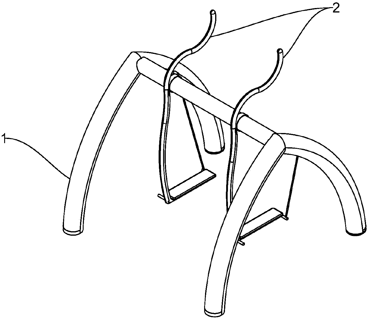
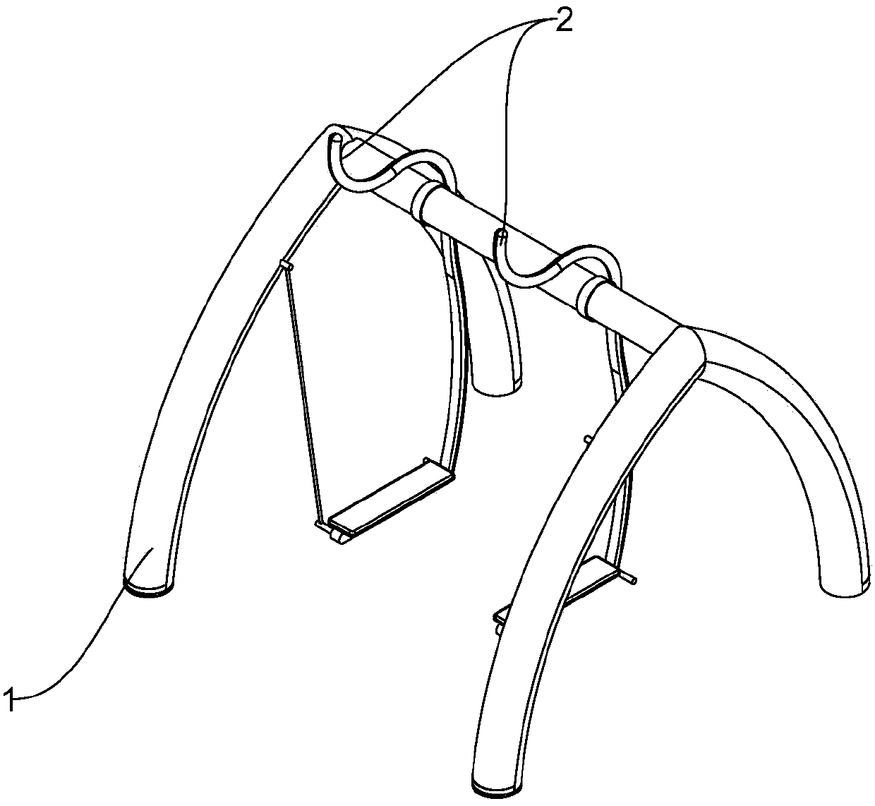
[0019] The advantage of the spacewalking machine with movable handle of the present invention is: the pedal, the pedal body and the joint of the pedal body and the crossbeam are all in the same vertical plane, so when people stand on the pedal and move, the pedal will not An extra torque is applied to the joint between the pedal body and the crossbeam, and the service life is longer. In addition, there are movable handles. When people move on this space walking machine, the movement law is closer to walking on the real road, and the experience is better. .

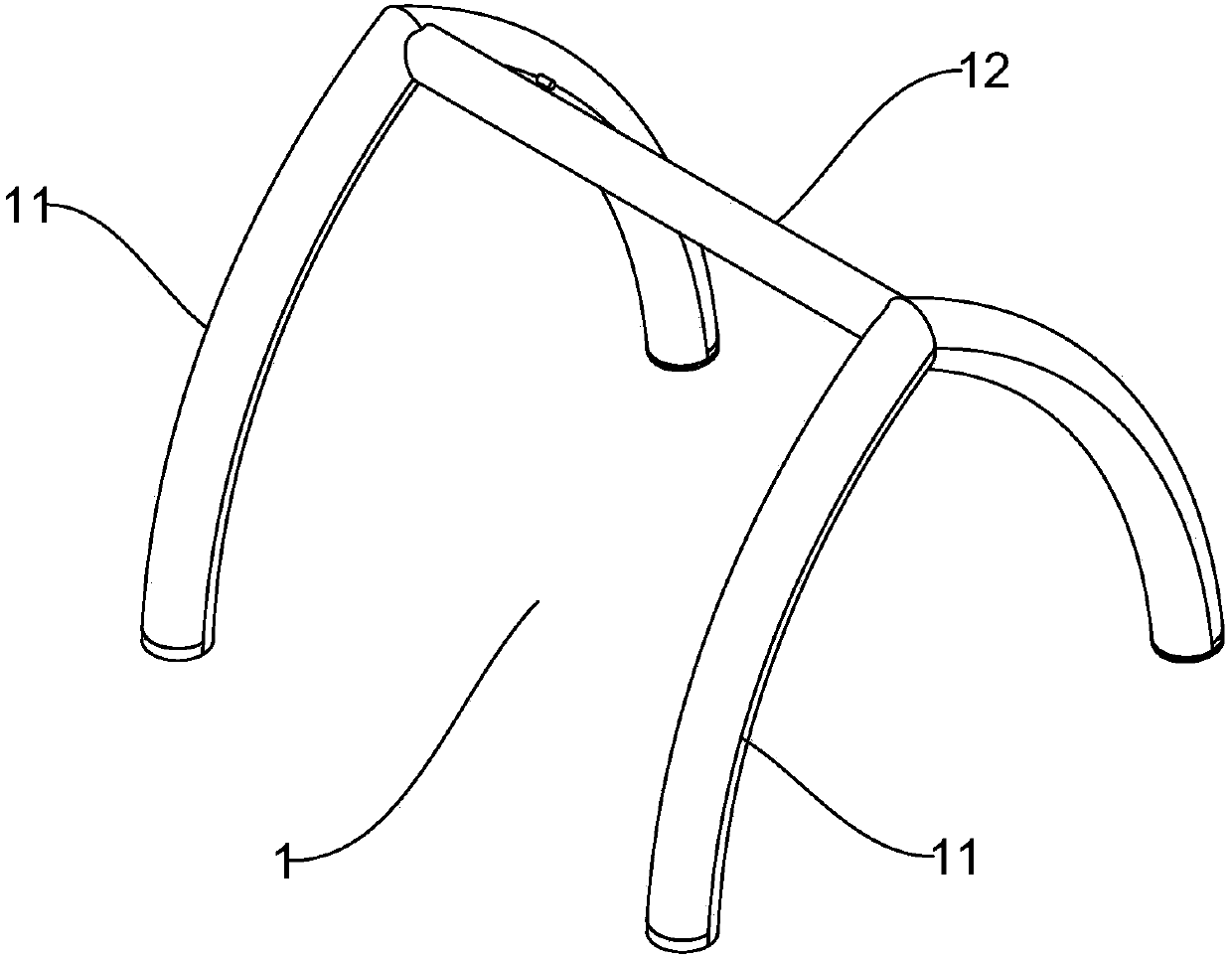
[0020] like figure 1 , figure 2 As shown, a space walker with a movable handle includes a bracket 1 and two pedal assemblies 2 arranged ...


PUM


Abstract

The invention discloses a spacewalking machine with movable handles, which comprises a bracket and two step bar assemblies arranged in parallel, and the bracket includes two "Λ" shaped support bars arranged parallel to each other and vertically and Horizontally arranged beams, the two ends of the beams are vertically connected to the corners of the "Λ"-shaped support rods; the pedal assembly includes a pedal body, a pedal and a connecting rod. The advantage of the spacewalking machine with movable handle of the present invention is: the pedal, the pedal body and the joint of the pedal body and the crossbeam are all in the same vertical plane, so when people stand on the pedal and move, the pedal will not An extra torque is applied to the joint between the pedal body and the crossbeam, and the service life is longer. In addition, there are movable handles. When people move on this space walking machine, the movement law is closer to walking on the real road, and the experience is better. .

Description

technical field [0001] The invention relates to a space walking machine, more precisely a space walking machine with movable handles. Background technique [0002] Chinese utility model patent CN201120359095.8 discloses a space walker, which includes a column fixed on the ground, a U-shaped handle fixedly installed in front of the upper part of the column, a fixed shaft fixedly installed on the inner side of the upper part of the column, and a bearing mounted on the fixed shaft. The fork on the top, the step bar fixed on the inner side of the lower end of the fork, the pedal installed on the step bar. An inner limit mechanism is also installed between the fixed shaft and the fork. The inner limit mechanism includes a limit sleeve fixed on the outer side of the upper end of the swing rod with an upper limit block, an outer cover fixed on the column with a lower limit block, and a sleeve installed in the outer cover and located between the lower limit block and the fixed shaf...

Claims


Application Information

Patent Timeline
IPC IPC(8): A63B22/00
CPCA63B22/001A63B22/0061
Inventor 曹国平
Owner 曹国平
Why Eureka
Try Eureka