
Two-way chamfering tool

A chamfering tool and chamfering technology, applied in the direction of lathe tools, cutting blades, manufacturing tools, etc., can solve the problems of poor adaptability, non-adjustable elastic stiffness, increased tool change time, etc., and achieve operability Strong, adaptable, stable and controllable effect

Pending Publication Date: 2018-02-23
MIANYANG MIANGONG TOOLS
View PDF0 Cites 2 Cited by
  • Summary
  • Abstract
  • Description
  • Claims
  • Application Information

AI Technical Summary

Problems solved by technology

[0003] The main disadvantages of the current two schemes are: first, the cost is high, the above two processing methods use three or two cutting tools, and the number of cutting tools is large; second, the efficiency is low. After the front chamfering and front chamfering, the workpiece must be turned over, and then the back chamfering will be processed, which increases the man-hours of re-clamping, and increases the tool changing time, which is not suitable for mass production.
[0004] There are also those who assemble the chamfering blade on the boring knife, such as the name of the patent document: a combined tool suitable for boring and chamfering on both sides of the hole, which is installed on the side wall of the boring knife parallel to its length direction The groove, and then cooperate with the spring steel, through the force exerted by the hole wall during the drilling process, the chamfering blade is pressed into the installation groove, so that after the chamfering blade is chamfered at the bottom, it can pass through the hole smoothly, and then proceed Reverse chamfering, so that it can realize double-sided chamfering without changing the tool. The disadvantage is that in order to ensure the smooth completion of the chamfering operation, its elastic stiffness must meet the rated requirements, and the stiffness is too small to complete the rated size. If the chamfering operation is too large, it cannot be retracted into the installation groove under the rated pressure, which will affect the quality of the drilling hole. Once the installation is completed, its elastic stiffness cannot be adjusted, and it cannot adapt to the needs of different chamfering sizes. In the case of chamfering with different sizes, it can only be realized by changing the chamfering tool, and the adaptability is not strong

Method used


Image

  • Two-way chamfering tool
  • Two-way chamfering tool
  • Two-way chamfering tool

Examples


Embodiment Construction

[0030] The present invention will be further described in detail below in conjunction with the accompanying drawings, so that those skilled in the art can implement it with reference to the description.

[0031] It should be understood that terms such as "having", "comprising" and "including" as used herein do not entail the presence or addition of one or more other elements or combinations thereof.

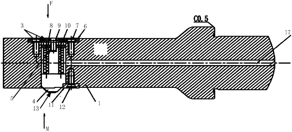
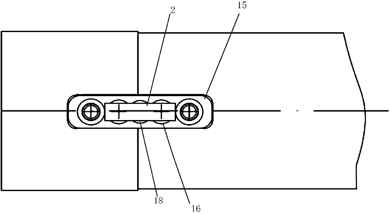
[0032] Figure 1-3 It shows an implementation form of a bidirectional chamfering tool according to the present invention, which includes:

[0033] The knife body 1 is provided with a square hole 2 perpendicular to the length direction of the knife body at the preset position of the front end, and one end of the square hole is detachably connected with a fixing part 3;

[0034] The two-way chamfering blade 4 is used to perform chamfering operations on the front and back sides simultaneously during hole processing; its connection end is connected to the fixing piece through an adj...


PUM


Abstract

The invention discloses a two-way chamfering tool which comprises a tool body and a two-way chamfering blade, wherein a square hole perpendicular to the length direction of the tool body is formed ina preset position at the front end of the tool body; a fixing part is detachably connected with one end of the square hole; the connecting end of the two-way chamfering blade is connected with the fixing part through an adjusting mechanism capable of adjusting the elastic force; a cutting edge end is arranged in the square hole of the tool body through a press plate arranged at the other end of the square hole; and a cutting edge of the two-way chamfering blade protrudes from the surface of the tool body at a preset height. The two-way chamfering tool provided by the invention has the advantages that through the adjusting mechanism capable of adjusting the elastic force, the elastic force of the two-way chamfering tool can be adjusted, so that the pressure of the two-way chamfering blade can be adjusted when the two-way chamfering blade is pressed into the tool body; accordingly, the chamfering size can be adjusted according to the actual usage demand during the two-way chamfering operation; the operability and the applicability are higher; and the stability is controllable.

Description

technical field [0001] The invention relates to a tool for use in tool machining. More specifically, the present invention relates to a bi-directional chamfering tool for use in drilling situations. Background technique [0002] In the current drilling process, it is necessary to meet the accuracy requirements of the hole and the quality of the hole wall. If chamfering is required on both sides of the hole, the usual processing method is to first bore the hole, and then reverse the front Then turn the workpiece over and chamfer the other side; or use a combined boring tool (a combination tool for boring and front chamfering) to complete the boring and front chamfering in one process, and then turn over and chamfer the other side; above Both processing methods use two cutting tools. [0003] The main disadvantages of the current two schemes are: first, the cost is high, the above two processing methods use three or two cutting tools, and the number of cutting tools is large...

Claims


Application Information

Patent Timeline
Patent Type & Authority Applications(China)
IPC IPC(8): B23B27/16
CPCB23B27/1614B23B2205/02
Inventor 宋世强刘燕
Owner MIANYANG MIANGONG TOOLS
Learn More