
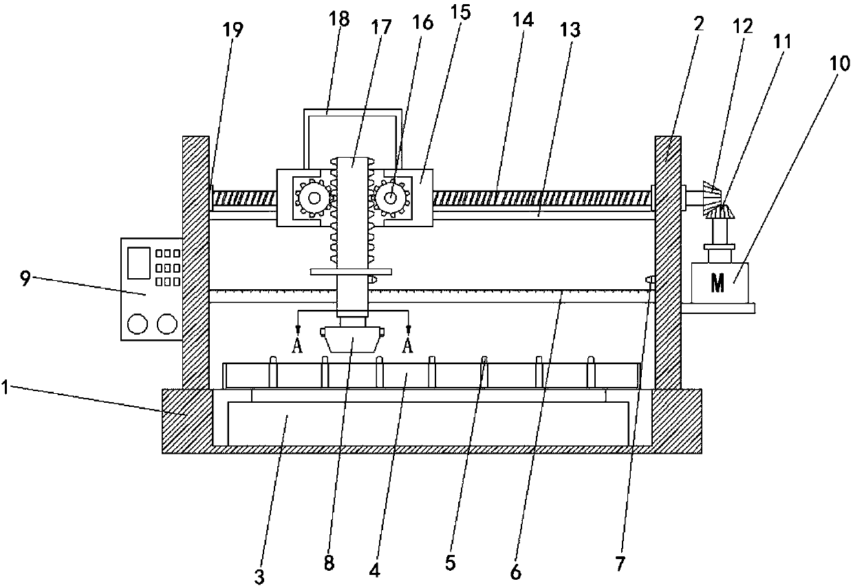
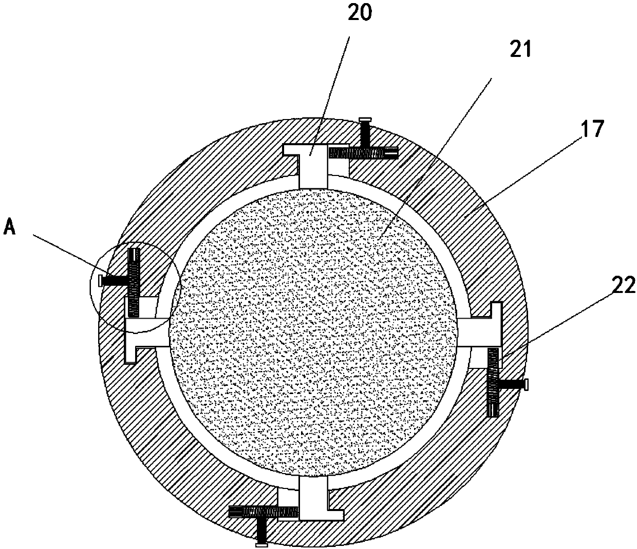
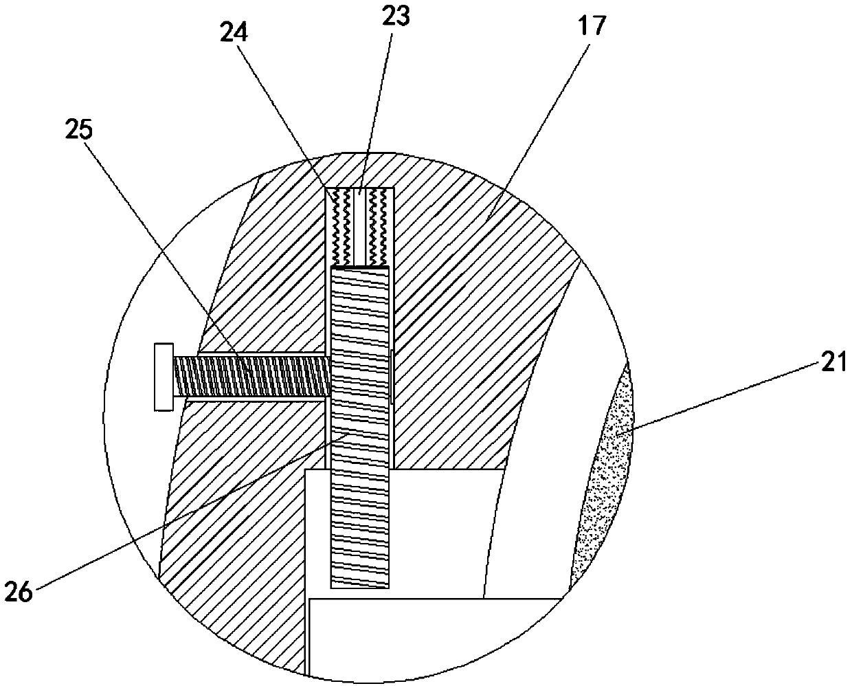
Grinding wheel production scraping device

A scraping and grinding wheel technology, used in grinding devices, metal processing equipment, grinding/polishing equipment, etc., can solve the problems of easy generation of bridges, difficult to eliminate, difficult to distribute evenly, etc., to achieve convenient scraper, easy operation , good practical effect

Inactive Publication Date: 2018-02-23
郭伟
View PDF6 Cites 5 Cited by
  • Summary
  • Abstract
  • Description
  • Claims
  • Application Information

AI Technical Summary

Problems solved by technology

Pour in one time, the material is too concentrated, it is not easy to distribute evenly, and the difference in bulk density is likely to be caused by the place where the stirring rod passes and the place where it does not pass when stirring the material
Due to the finer particle size of the molding material, bridge phenomenon is easy to occur, and this phenomenon is difficult to eliminate, the finer the particle size of the molding material, the more serious the bridge phenomenon
This type of device can only ensure that the material on the surface is scraped flat, but the material on the lower layer cannot guarantee its uniformity due to the bridge phenomenon. It may be that the material in the serious bridge is empty, and the material in other places is solid. Such unevenness will directly lead to The strength and hardness of the product are uneven, resulting in unstable product quality. Therefore, we propose a scraping device for grinding wheel production to solve this problem.

Method used


Image

  • Grinding wheel production scraping device
  • Grinding wheel production scraping device
  • Grinding wheel production scraping device

Examples


Embodiment Construction

[0018] The following will clearly and completely describe the technical solutions in the embodiments of the present invention with reference to the accompanying drawings in the embodiments of the present invention. Obviously, the described embodiments are only some, not all, embodiments of the present invention.

[0019] In describing the present invention, it should be understood that the terms "upper", "lower", "front", "rear", "left", "right", "top", "bottom", "inner", " The orientation or positional relationship indicated by "outside", etc. is based on the orientation or positional relationship shown in the drawings, and is only for the convenience of describing the present invention and simplifying the description, rather than indicating or implying that the referred device or element must have a specific orientation, so as to Specific orientation configurations and operations, therefore, are not to be construed as limitations on the invention.

[0020] refer to Figure ...


PUM


Abstract

The invention discloses a grinding wheel production scraping device. The grinding wheel production scraping device comprises a base, a groove is formed in the upper end of the base, a first driving motor with an output shaft facing upwards is arranged at the inner bottom of the groove, and a grinding wheel forming mould is connected to the output end of the first driving motor; two support platesare further symmetrically arranged at the upper end of the base, two bearings are symmetrically arranged on the side walls of the opposite sides of the two support plates, a first threaded rod is arranged between the two bearings, one end of the first threaded rod penetrates through one support plate and is provided with a second bevel gear, a supporting plate and a second driving motor arranged on the supporting plate are arranged on the side wall of one support plate, and a rotating rod is connected to the driving end of the second driving motor through a connecting shaft. The grinding wheelproduction scraping device is convenient to operate; fast, effective and precise scraping can be conducted on grinding wheels, and the horizontal displacement and height adjustment can be conducted;besides, a scraping plate can be conveniently replaced, and the grinding wheel production scraping device has high practicability.

Description

technical field [0001] The invention relates to the technical field of grinding wheel hanging, in particular to a scraping device for grinding wheel production. Background technique [0002] in grinding wheel production. The feeding and scraping devices currently used in the market are generally one-time pouring, first throwing and then scraping. Pour in one time, the material is too concentrated, it is not easy to distribute evenly, and the difference in bulk density is likely to be caused by the place where the stirring rod passes and the place where it does not pass when stirring the material. Because the particle size of the molding material is finer, bridge phenomenon is easy to occur, and this phenomenon is difficult to eliminate, the finer the particle size of the molding material, the more serious the bridge phenomenon is. This type of device can only ensure that the material on the surface is scraped flat, but the material on the lower layer cannot guarantee its u...

Claims


Application Information

Patent Timeline
IPC IPC(8): B24D18/00
CPCB24D18/0009
Inventor 郭伟
Owner 郭伟
Learn More