
Multi-row lead frame structure

A lead frame and frame technology, applied in the direction of household components, household appliances, and other household appliances, can solve the problem that layering cannot realize one injection or multiple rows, and achieve the effect of uniform force

Inactive Publication Date: 2018-02-23
长电科技(宿迁)有限公司
View PDF5 Cites 0 Cited by
  • Summary
  • Abstract
  • Description
  • Claims
  • Application Information

AI Technical Summary

Problems solved by technology

[0013] The technical problem to be solved by the present invention is to provide a multi-row lead frame structure for the above-mentioned prior art, which can solve the problem of delamination and the inability to realize multiple or multiple rows of existing small packages during demoulding.

Method used


Image

  • Multi-row lead frame structure
  • Multi-row lead frame structure
  • Multi-row lead frame structure

Examples


Embodiment Construction

[0042] The present invention will be further described in detail below in conjunction with the accompanying drawings and embodiments.

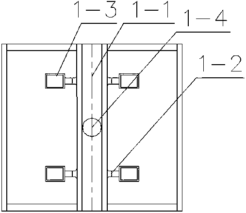
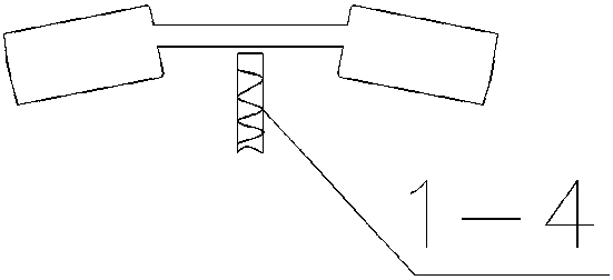
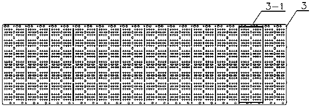
[0043] like Figure 3~Figure 5 As shown, a multi-row lead frame structure in this embodiment includes several frame units 3-1, each frame unit 3-1 is composed of two left and right column units 3-2, each column unit 3 -2 is composed of multiple rows of unit structures 3-3, each unit structure 3-3 is composed of several side-by-side products 3-4, and several main channels are arranged vertically between the left and right columns of units 3-2 Glue punching holes 3-5, at least one of the two adjacent sprue punching holes 3-5 are provided with several virtual runner punching holes 3-6 along the horizontal direction , the virtual runner hole 3-6 is located above or below the unit structure 3-3;

[0044] The number of unit structures 3-3 in each column unit 3-2 is 14 rows, 16 rows, 18 rows or 20 rows.

[0045] see Image 6 , a mold structure wi...


PUM


Abstract

The invention relates to a multi-row lead frame structure. The multi-row lead frame structure comprises a plurality of frame units (3-1). Each of the frame units (3-1) is composed of left and right line units (3-2). Each of the line units (3-2) is composed of multiple lines of unit structures (3-3); each of the unit structures (3-3) is composed of a plurality of parallel products (3-4); a plurality of main runner flushing glue holes (3-5) are formed between the left and right line units (3-2) along the vertical direction; and a plurality of virtual runner flushing glue holes (3-6) are formed in two sides of at least one of the two adjacent main runner flushing glue holes (3-5) along the horizontal direction. According to the multi-row lead frame structure provided by the invention, by forming the virtual runner flushing glue holes among lines of the lead frame, waste glue for demolding and ejecting by means of a molding compound is formed on the peripheries of the unit structures of the lead frame during encapsulation, so that the lead frame is uniformly stressed during demolding.

Description

technical field [0001] The invention relates to a multi-row lead frame structure, which belongs to the technical field of semiconductor packaging. Background technique [0002] see figure 1 , figure 2 , when the lead frame of the existing small package is plastic-encapsulated, the following steps are generally followed: [0003] Step 1. Preheat the product to be plastic sealed; [0004] Step 2. Transport the product to the plastic sealing mold; [0005] Step 3: Preheat the plastic sealing material cake and close the mold for injection molding, and press-inject the liquid plastic sealing material into the main channel 1-1; [0006] Step 4: The molding compound fills the product cavity 1-3 along the gates 1-2 on both sides of the main channel; [0007] Step 5, open the mold, the thimble pin 1-4 of the lower mold withstands the waste rubber in the main channel to make the product leave the mold; [0008] Step 6. Glue flushing. The demoulded product is transported to the ...

Claims


Application Information

Patent Timeline
Patent Type & Authority Applications(China)
IPC IPC(8): B29C45/32B29C45/40B29L31/34
Inventor 周正伟刘红军王赵云张波徐赛
Owner 长电科技(宿迁)有限公司
Learn More