Dynamic spiral landscape device

A spiral and landscape technology, which is applied to stage installations, special decorative structures, installations used in theaters and circuses, etc., can solve the problems that cannot be separated for independent control, the driving force required for rotation is large, and the scene effect is monotonous. Achieve the effect of ensuring installation strength and operational reliability, good landscape effect, and unique and ingenious design

Pending Publication Date: 2018-02-23
ZHEJIANG JIAHE CULTURE TECH CO LTD
View PDF5 Cites 0 Cited by
  • Summary
  • Abstract
  • Description
  • Claims
  • Application Information

AI Technical Summary

Problems solved by technology

"The turntable frame and the ring guide rail are spliced ​​together by channel steel by bolt connection. On the one hand, it is not suitable for large-scale scenes such as large-scale cultural squares, tourist attractions, and amphitheatres. Large-scale structures have higher structural requirements, and The dri

Method used


Image

  • Dynamic spiral landscape device
  • Dynamic spiral landscape device
  • Dynamic spiral landscape device

Examples


Example Embodiment

[0032] Example one

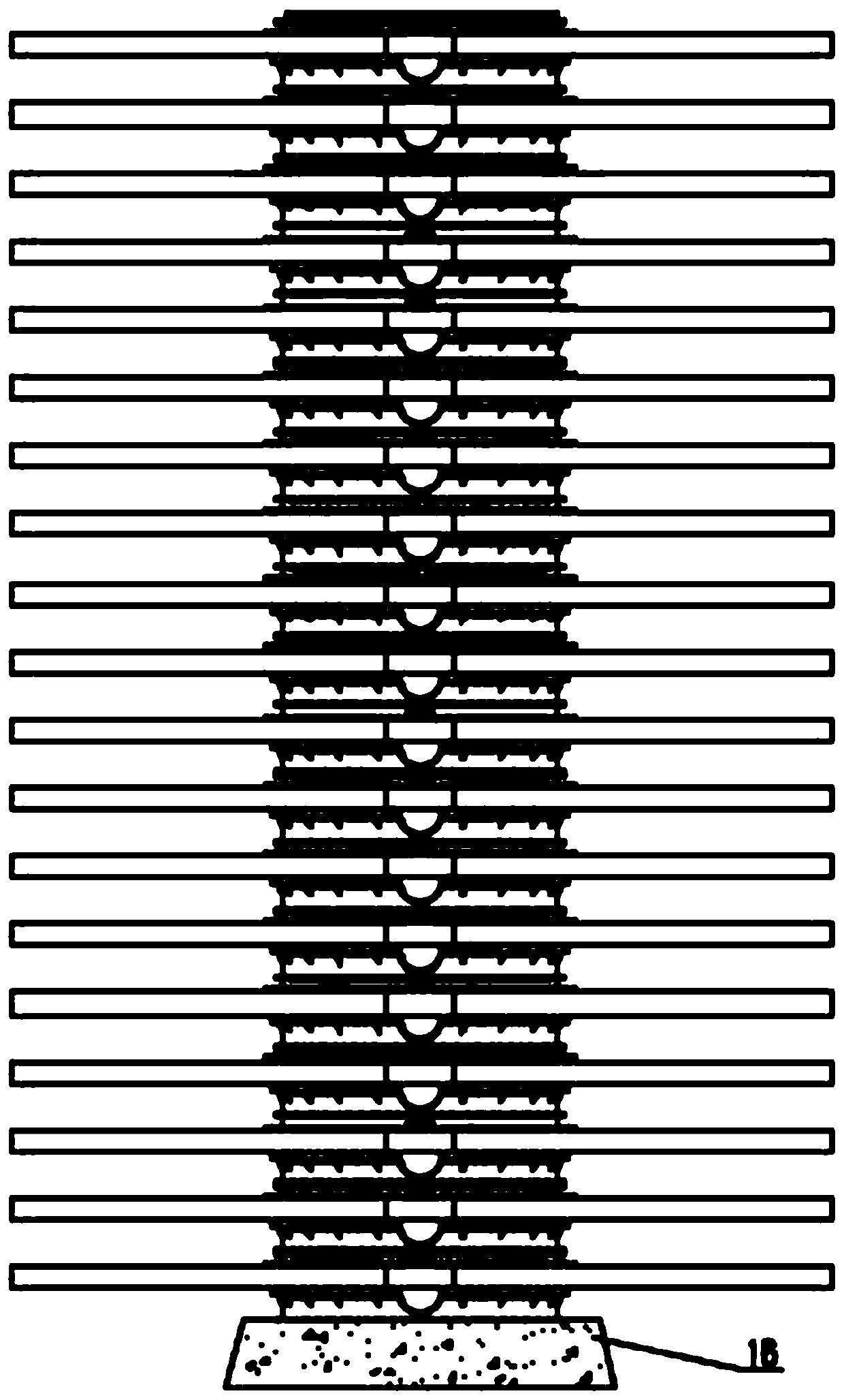
[0033] Such as Figure 1-3 As shown, the present invention can be assembled into figure 1 The cylindrical structure shown also includes a base 16. Any of the gear-driven rotating mechanisms described as an independent rotating unit. The lower flange 10 of the fixed ring 1 of the gear-driven rotating mechanism at the lower end of the columnar structure is connected to the base 16 and fixedly installed.

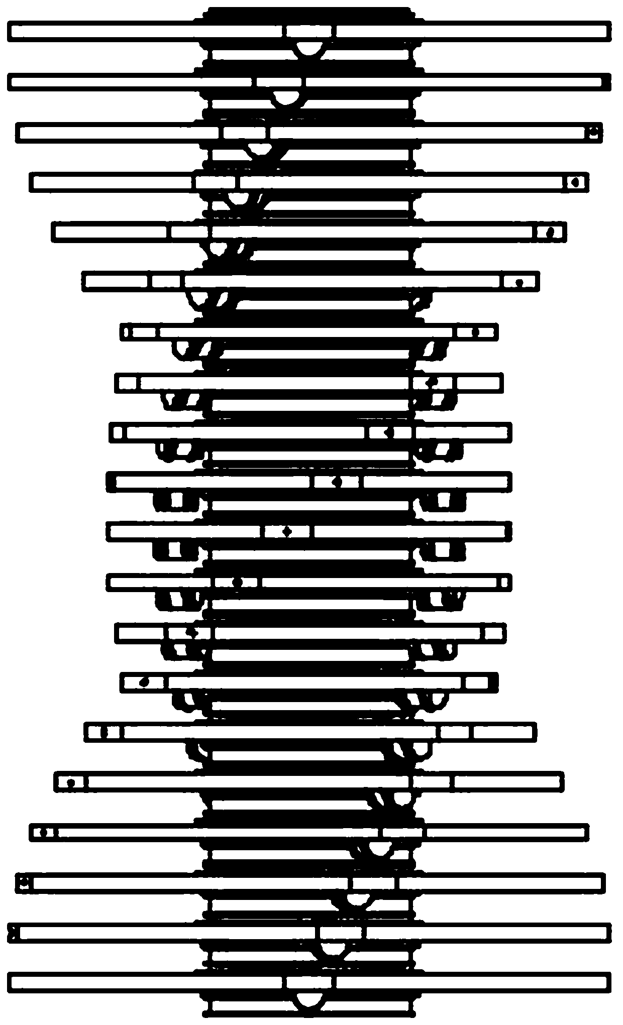
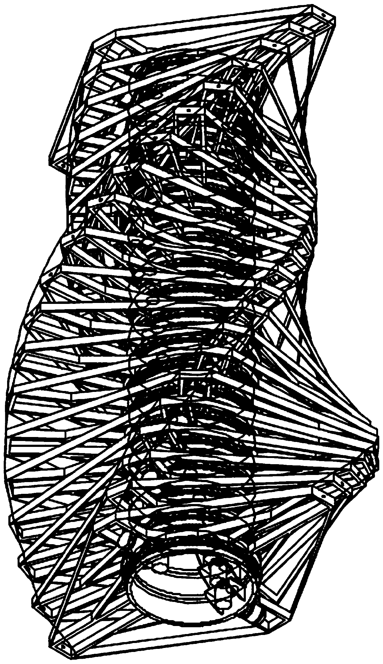
[0034] Each rotation unit includes an independent rotation drive mechanism, and the rotation angle of the rotation unit is precisely controlled by a servo motor. When the rotation angle of the rotation unit is arranged in an arithmetic sequence, it can be as follows Figure 2-3 Spiral effect shown.

[0035] Such as Figure 4-6 Shown is a schematic structural diagram of the rotating unit. The fixed ring 1 is a hollow cylindrical structure. The present invention installs two oppositely arranged along the center of the fixed ring 1 on the hollow inner wall of the f...

Example Embodiment

[0036] Example two, such as Figure 7 As shown, the rotating frame 2 is a rhombus plate structure, the rhombus plate structure is provided with an installation groove, the installation groove is installed with a fuel tank 11, and the rhombus plate structure is also provided with Fire hole 12. As a way, the fuel tank 11 is arranged in the installation groove on the lower surface of the rotating frame 2 and is restrained by a restraint belt. The restraint belt is not restricted in material, and may be metal, leather, or other materials. The fuel tank 11 and the spray hole 12 are connected to a control circuit, and the control circuit can control the spray time. The fire blast hole 12 is arranged at the end point far away from the center of the fixing ring 1, so that after the combination of the present invention is installed, the fire blast will not affect other components and reduce component material damage and danger.

Example Embodiment

[0037] Example three, such as Figure 8 As shown, the rotating frame 2 is sheathed with the cover, and preferably, the inner surface of the cover can just be sheathed on the outer surface of the rotating frame 2. A through hole is provided in the center of the casing, and the diameter of the through hole is larger than the outer diameter of the upper flange 9 of the fixed ring 1. In this embodiment, the upper flange 9 of the fixed ring 1 is higher than the rotating frame 2, and the through hole of the cover is sleeved outside the upper flange 9. The cover is provided with fire holes 12 corresponding to the fire holes 12 of the rotating frame 2.


PUM


Abstract

The invention discloses a dynamic spiral landscape device. The dynamic spiral landscape device comprises a plurality of rotating units; each rotating unit comprises a fixed ring and a rotating frame arranged outside the fixed ring in a sleeving mode and can rotate relatively around the center of the fixed ring; the rotating frames are connected with rotating driving mechanisms; upper flanges are arranged on the upper end faces of the fixed rings, and lower flanges are arranged on the lower end faces of the fixed rings; and the rotating units are stacked in sequence through connection of the upper flanges and the lower flanges of the fixed rings. The dynamic spiral landscape device can be suitable for large cultural squares, tourist attractions and outdoor theaters, the scene effect is richand colorful through the dynamic spiral landscape device, and the spiral rotation effect can be achieved.

Description

technical field [0001] The invention relates to a dynamic spiral landscape device. Background technique [0002] Existing landscape props all perform simple movements and can only achieve single functions such as lifting or overall rotation, so there are great limitations in use. The structure is single, the action is relatively monotonous when used, and the scene effect is poor. [0003] At present, the existing Chinese invention patent "A Rotating High Platform Prop" discloses a stage rotating device, "comprising a turntable frame, a central shaft, a shaft sleeve, a circular guide rail, and a trolley. The turntable frame is provided with a high platform. The circular guide rail is arranged under the turntable frame, the upper part of the trolley is fixedly installed under the turntable frame, the lower part of the trolley is in contact with the circular guide rail, a connecting beam is arranged in the center of the turntable frame, and the center of the upper part of the ...

Claims


Application Information

Patent Timeline
IPC IPC(8): B44C5/00A63J5/02
CPCA63J5/02B44C5/00
Inventor 阮小华陈俊黄敏慧汪汐卢妙芳徐利燕
Owner ZHEJIANG JIAHE CULTURE TECH CO LTD
Why Eureka
Try Eureka