Propulsion mechanism

A technology of propulsion mechanism and push plate, which is applied in the direction of conveyors, conveyor objects, transportation and packaging, etc. It can solve the problems of high cost, inability to adjust, fix, etc., and achieve the effect of low cost, convenient stroke adjustment and simple structure

Inactive Publication Date: 2018-02-23
苏州金牛精密机械有限公司
View PDF5 Cites 0 Cited by
  • Summary
  • Abstract
  • Description
  • Claims
  • Application Information

AI Technical Summary

Problems solved by technology

[0002] The propulsion mechanism is often used in industrial production, which can play the role of: feeding, clamping, positioning, etc. When the shape and size of the workpiece change, the stroke of the propulsion mechanism also needs to change, and the existing stroke of the propulsion mechanism is often It is fixed and cannot be adjusted; the propulsion mechanism with adjustable stroke has complex structure and high cost

Method used


Image

  • Propulsion mechanism
  • Propulsion mechanism

Examples


Embodiment Construction

[0015] The technical solution of the present invention will be described in further non-limiting detail below in combination with preferred embodiments and accompanying drawings.

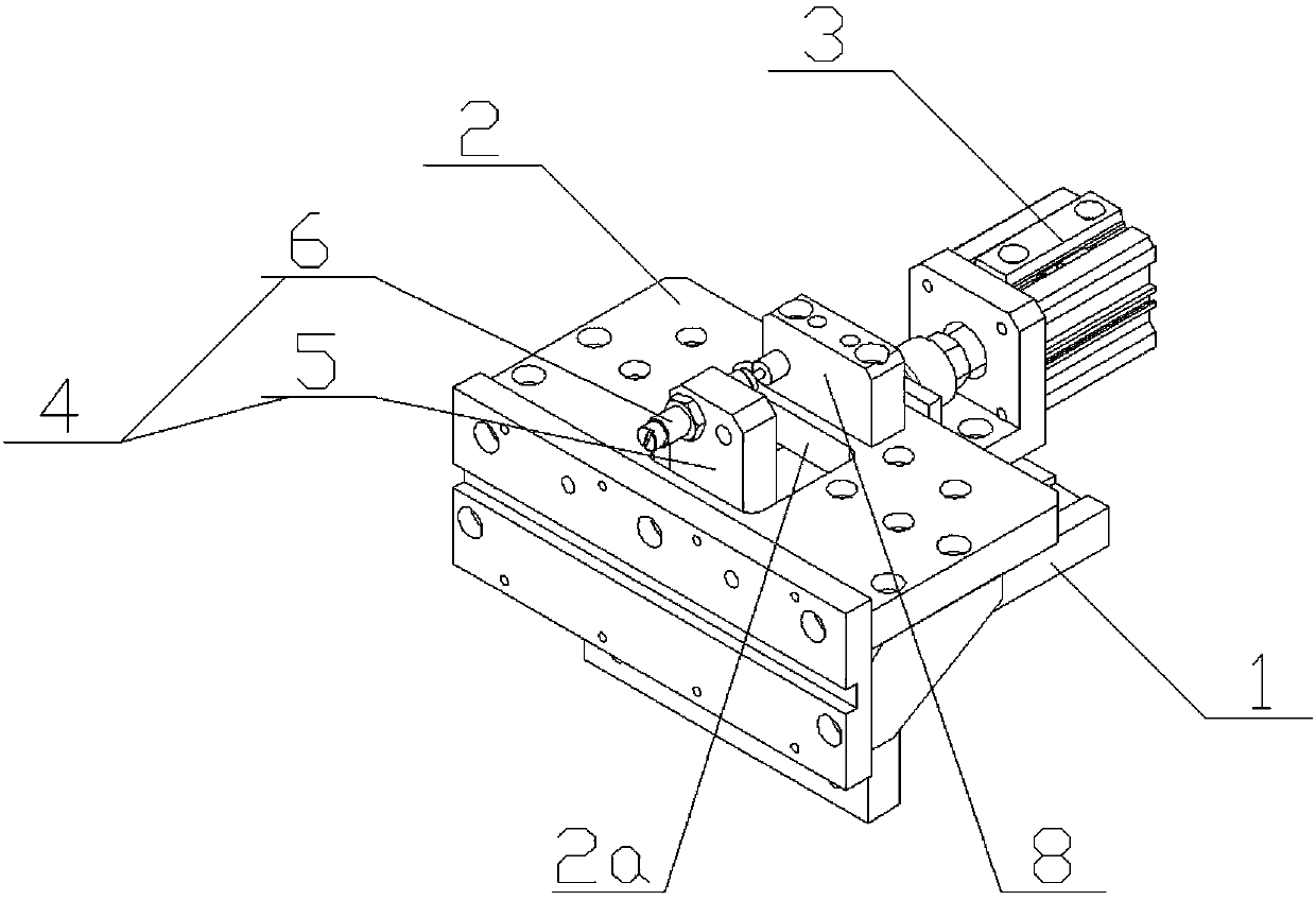
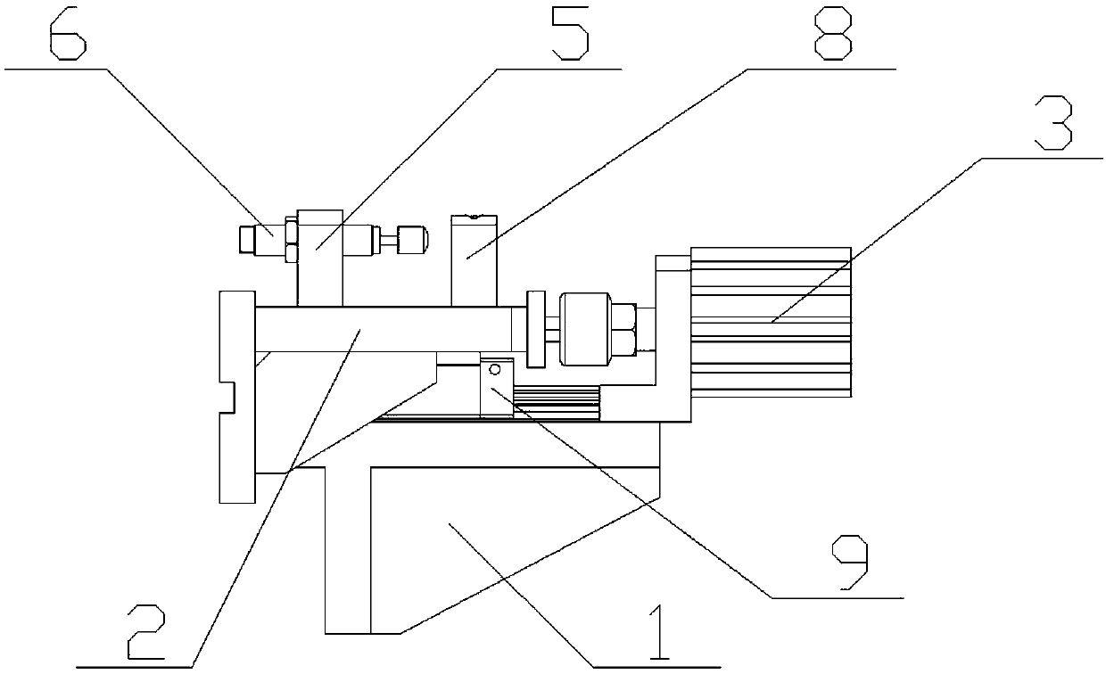
[0016] Such as figure 1 and figure 2 As shown, a propulsion mechanism corresponding to a preferred embodiment of the present invention includes: a base 1 , a push plate 2 , a driving device 3 , a limiting assembly 4 and a sliding guide rail 9 .

[0017] The sliding guide rail 9 is installed on the base 1, and the push plate 2 is connected on the sliding guide rail 9, so that the push plate 2 can move along the axial direction of the sliding guide rail 9.

[0018] In this embodiment, the driving device 3 is an air cylinder, which may also be a hydraulic cylinder or the like, and is used to drive the push plate to move in a straight line.

[0019] The limit assembly 4 includes a support plate 5 connected to the base 1 and a stopper 6 connected to the support plate 5. The stopper 6 may be a screw or...


PUM


Abstract

The invention discloses a propulsion mechanism. The propulsion mechanism is characterized by comprising a base (1), a pushing plate (2) movably connected to the base (1), a driving device (3) for driving the pushing plate (2) to move and a limit component (4) connected to the base (1), and the position of the limit component (4) can be adjusted. According to the propulsion mechanism, by arrangingthe limit component adjustable in position, the stroke of the pushing plate can be adjusted; the structure is simple, the stoke adjustment is convenient and reliable, and the cost is low.

Description

technical field [0001] The invention relates to a propulsion mechanism. Background technique [0002] The propulsion mechanism is often used in industrial production, which can play the role of: feeding, clamping, positioning, etc. When the shape and size of the workpiece change, the stroke of the propulsion mechanism also needs to change, and the existing stroke of the propulsion mechanism is often It is fixed and cannot be adjusted; the propulsion mechanism with adjustable stroke has complex structure and high cost. Contents of the invention [0003] The object of the present invention is to provide a stroke-adjustable propulsion mechanism aiming at the above-mentioned defects in the prior art. [0004] In order to achieve the purpose of the above invention, the present invention adopts the following technical solutions: a propulsion mechanism comprising a base, a push plate movably connected to the base, a driving device for driving the push plate to move, and a drive ...

Claims


Application Information

Patent Timeline
Patent Type & Authority Applications(China)
IPC IPC(8): B65G47/82B65G25/08
CPCB65G25/08B65G47/82
Inventor 周建荣
Owner 苏州金牛精密机械有限公司
Why Eureka
Try Eureka