
System for monitoring potentiostat in cathode protection system in real time

A potentiostat and cathodic protection technology, applied in the field of intelligent monitoring, can solve problems such as the inability to understand the parameter values ​​of the potentiostat in real time, the inability to realize the normal operation of long-distance monitoring equipment, and the long-distance distribution of underground pipe networks. Achieve the effects of strong real-time performance and practicality, simple structure and easy operation

Inactive Publication Date: 2018-02-23
江苏飞视文化发展有限公司
View PDF6 Cites 2 Cited by
  • Summary
  • Abstract
  • Description
  • Claims
  • Application Information

AI Technical Summary

Problems solved by technology

However, the ordinary potentiostat currently used has only the most basic control functions. During normal work, it is placed indoors, and the relevant technical parameter electrical signals are transmitted to the underground pipelines and test piles by the indoor personnel through wired control; especially When the management personnel manage the various technical parameters in the potentiostat, they need to go to the location where the potentiostat is placed to make corresponding adjustments
Due to the long-distance distribution of the underground pipe network in actual operation, it has caused a lot of inconvenience to the daily management and operation. It takes a lot of time, and the management personnel cannot understand the parameter values ​​of the potentiostat in real time, and it is impossible to realize long-distance monitoring. and ensure the normal operation of the equipment

Method used


Image

  • System for monitoring potentiostat in cathode protection system in real time

Examples


Embodiment Construction

[0019] Below in conjunction with accompanying drawing, technical scheme of the present invention is described in further detail:

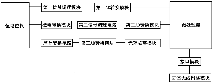
[0020] like figure 1 As shown, a system for real-time monitoring of a potentiostat in a cathodic protection system includes a potentiostat, a data acquisition terminal, a microprocessor, an interface module and a GPRS wireless network module, and the data acquisition terminal includes a first signal conditioning module, a first AD conversion module, magnetoelectric conversion module, second signal conditioning circuit, second AD conversion module, differential conversion circuit, third AD conversion module and optocoupler isolation module; wherein,

[0021] The potentiostat is connected to the first signal conditioning module, the magnetoelectric conversion module, and the differential conversion circuit respectively, and the first signal conditioning module, the first AD conversion module, the microprocessor, the interface module, and the GPRS wir...


PUM


Abstract

The invention discloses a system for monitoring a potentiostat in a cathode protection system in real time. The system comprises the potentiostat, a data acquisition terminal, a microprocessor, an interface module and a GPRS wireless network module, wherein the data acquisition terminal comprises a first signal conditioning module, a first AD conversion module, a magneto-electricity conversion module, a second signal conditioning circuit, a second AD conversion module, a differential transformation circuit, a third AD conversion module and an optocoupler isolation module; the potentiostat is connected with the first signal conditioning module, the magneto-electricity conversion module and the differential transformation circuit, the first signal conditioning module, the first AD conversionmodule, the microprocessor, the interface module and the GPRS wireless network module are sequentially connected, the magneto-electricity conversion module, the second signal conditioning circuit, the second AD conversion module and the microprocessor are sequentially connected, and the differential transformation circuit, the third AD conversion module, the optocoupler isolation module and the microprocessor are sequentially connected. The system can monitor the state of the running potentiostat remotely in real time.

Description

technical field [0001] The invention relates to the technical field of intelligent monitoring, in particular to a system for real-time monitoring of a potentiostat in a cathodic protection system. Background technique [0002] With the development of the economy and the construction of the city, the number of buried, underwater and concrete metal pipes and metal facilities is increasing, and these metal pipes and metal facilities are prone to corrosion. In order to prevent corrosion of buried pipelines and improve their service life , cathodic protection is one of the main methods of anti-corrosion at present, and the cathodic protection device is the key equipment of the cathodic protection system. Regional cathodic protection is required for buried metal pipelines and metal equipment with high distribution density in the area [0003] At present, in order to solve the corrosion problems of buried metal pipelines and tank groups, forced current cathodic protection is often...

Claims


Application Information

Patent Timeline
IPC IPC(8): C23F13/22
CPCC23F13/22
Inventor 黄静范晓琴冯月娟
Owner 江苏飞视文化发展有限公司
Learn More