
Yarn dyeing device

A yarn dyeing and equipment technology, applied in the field of machinery, can solve the problems of reducing work efficiency, time-consuming and labor-intensive, etc., and achieve the effect of saving time and high efficiency

Active Publication Date: 2018-02-23
江苏中祥线带有限公司
View PDF5 Cites 7 Cited by
  • Summary
  • Abstract
  • Description
  • Claims
  • Application Information

AI Technical Summary

Problems solved by technology

[0003] At present, due to the needs of the market and customers, the yarn must be dyed. When dyeing the yarn, the yarn needs to be sent into the dyeing barrel for dyeing. However, many of the current dyeing equipment only have the function of dyeing. Yarn squeezing is done manually, which is time-consuming and labor-intensive, greatly reducing work efficiency

Method used


Image

  • Yarn dyeing device
  • Yarn dyeing device
  • Yarn dyeing device

Examples


Embodiment Construction

[0041] The following are specific embodiments of the present invention and in conjunction with the accompanying drawings, the technical solutions of the present invention are further described, but the present invention is not limited to these embodiments.

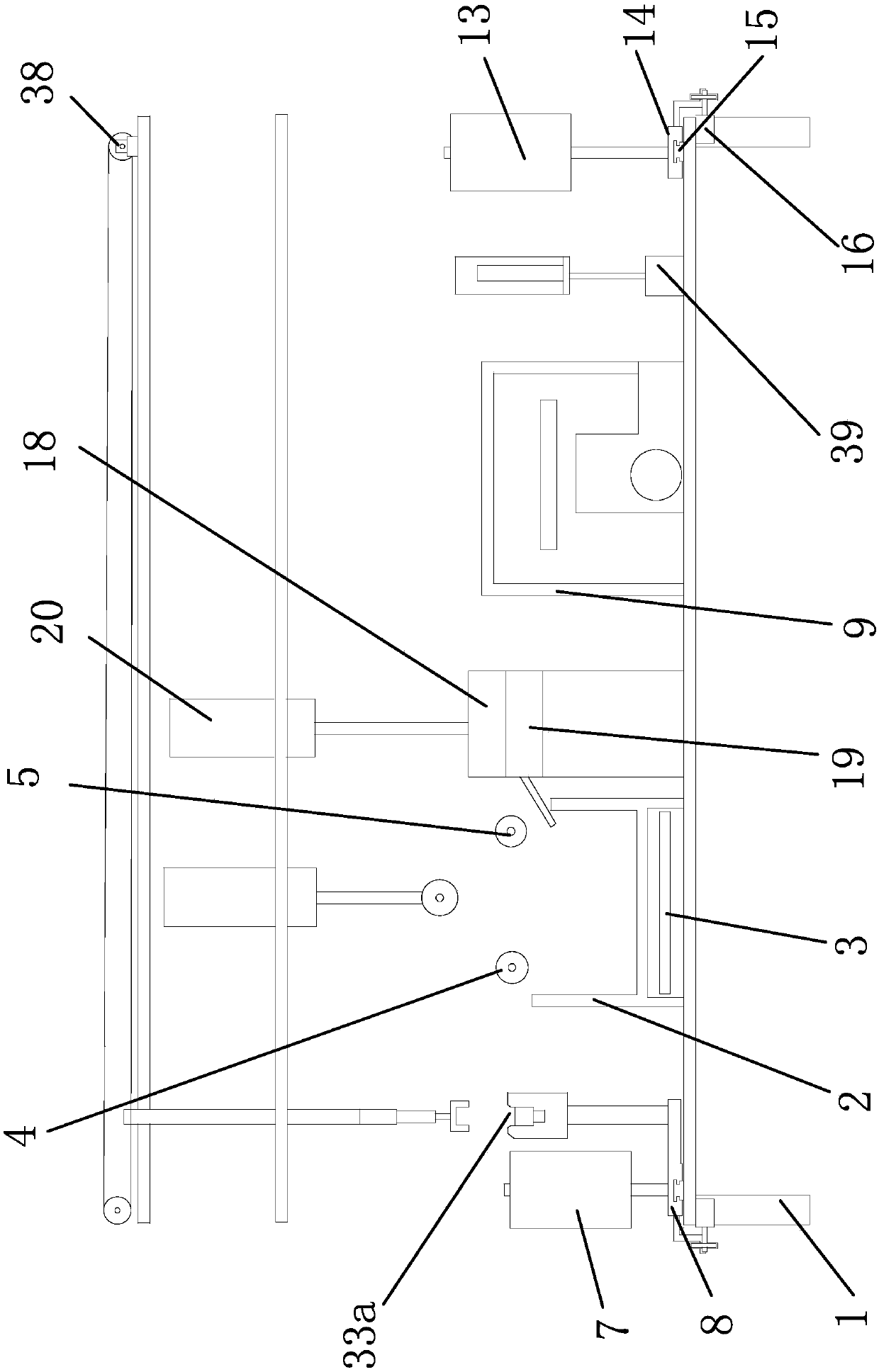
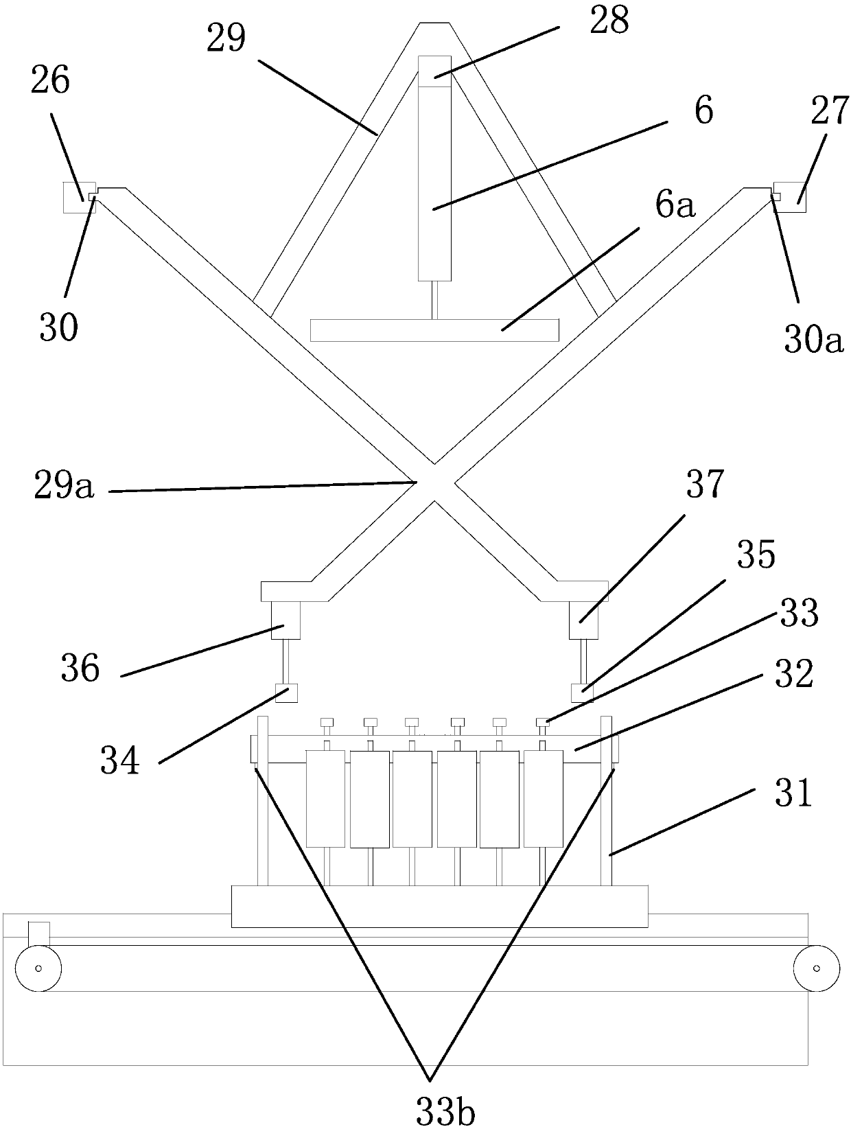
[0042] Such as Figures 1 to 6 As shown, a kind of yarn dyeing equipment comprises a frame 1, a dyeing box 2 with a cavity inside is arranged on the frame 1, a dye is arranged in the dyeing box 2, an electromagnetic heating coil 3 is arranged at the bottom of the dyeing box 2, and the dyeing The first roller 4 and the second roller 5 are arranged on the box 2, and the first roller 4 and the second roller 5 are parallel to each other; the hydraulic cylinder one 6 is fixed on the fixed frame, and the piston rod of the hydraulic cylinder one 6 is vertically downward, The piston rod end of hydraulic cylinder one 6 is fixedly provided with roller three 6a, and roller three 6a is positioned between roller one 4 and roller two 5;...


PUM


Abstract

The invention provides a yarn dyeing device and belongs to the technical field of machinery. The technical problems of low dyeing efficiency and the like of an existing dyeing device are solved. The yarn dyeing device includes a machine frame and is characterized in that the machine frame is provided with a dyeing box internally provided with a cavity, dye is disposed in the dyeing box, an electromagnetic heating ring is disposed on the lower portion of the dyeing box, the dyeing box is provided with a first roller and a second roller, and the first roller is parallel to the second roller. A first hydraulic cylinder is fixedly arranged on a fixing frame, a piston rod of the first hydraulic cylinder is vertically downwards, a third roller is fixedly arranged at the end of the piston rod ofthe first hydraulic cylinder, and the third roller is located between the first roller and the second roller. A plurality of yarn placing barrels are disposed on one side of the dyeing box. The yarn dyeing device has the advantage of being high in dyeing efficiency.

Description

technical field [0001] The invention belongs to the technical field of machinery, in particular to a yarn dyeing device. Background technique [0002] Yarn is divided into staple fiber yarn, which is made of staple fiber (natural staple fiber or chemical fiber cut fiber) through spinning, and is divided into ring-spun yarn, open-end spinning yarn, self-twist yarn, etc. ② Continuous filaments, such as natural silk and chemical fiber filaments, are divided into twisted or untwisted, smooth filaments or deformed filaments, etc. ③Short fiber and continuous filament combined yarn, such as polyester-cotton filament core-spun yarn, etc. The thread is made of two or more single yarns combined and twisted. [0003] At present, due to the needs of the market and customers, the yarn must be dyed. When dyeing the yarn, the yarn needs to be sent into the dyeing barrel for dyeing. However, many of the current dyeing equipment only have the function of dyeing. Yarn squeezing is done man...

Claims


Application Information

Patent Timeline
Patent Type & Authority Applications(China)
IPC IPC(8): D06B3/09D06B15/00D06B23/04D06B23/22
CPCD06B3/09D06B15/00D06B15/005D06B23/04D06B23/22
Inventor 陈晔
Owner 江苏中祥线带有限公司
Learn More