An evaporating tube combustion chamber

An evaporation tube and combustion chamber technology, applied in combustion chambers, continuous combustion chambers, combustion methods, etc., can solve the problems of limited atomization effect of large-scale particle size droplets, widen the stable working boundary, reduce the risk of flameout, reduce the The effect of smoke index

Active Publication Date: 2020-08-14
INST OF ENGINEERING THERMOPHYSICS - CHINESE ACAD OF SCI
View PDF6 Cites 0 Cited by
  • Summary
  • Abstract
  • Description
  • Claims
  • Application Information

AI Technical Summary

Problems solved by technology

The above-mentioned schemes improve the mixing effect of fuel and air by increasing the heat exchange area of ​​fuel and air in the evaporator tube, but these measures only enhance the heat exchange of oil and air, but do not change the liquid droplets from large-scale particles to small-scale particles. The crushing speed of particles, so the atomization effect of large-scale particle size droplets is very limited only by enhancing heat transfer

Method used


Image

  • An evaporating tube combustion chamber
  • An evaporating tube combustion chamber
  • An evaporating tube combustion chamber

Examples


Embodiment Construction

[0028] In order to make the object, technical solution and advantages of the present invention clearer, the present invention will be further described in detail below with reference to the accompanying drawings and examples.

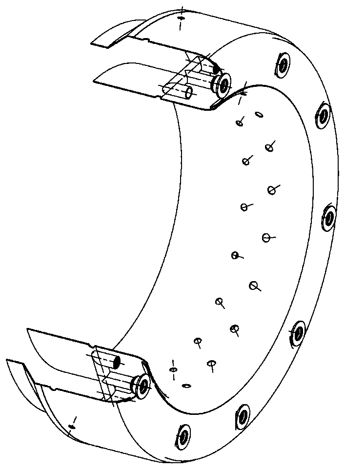
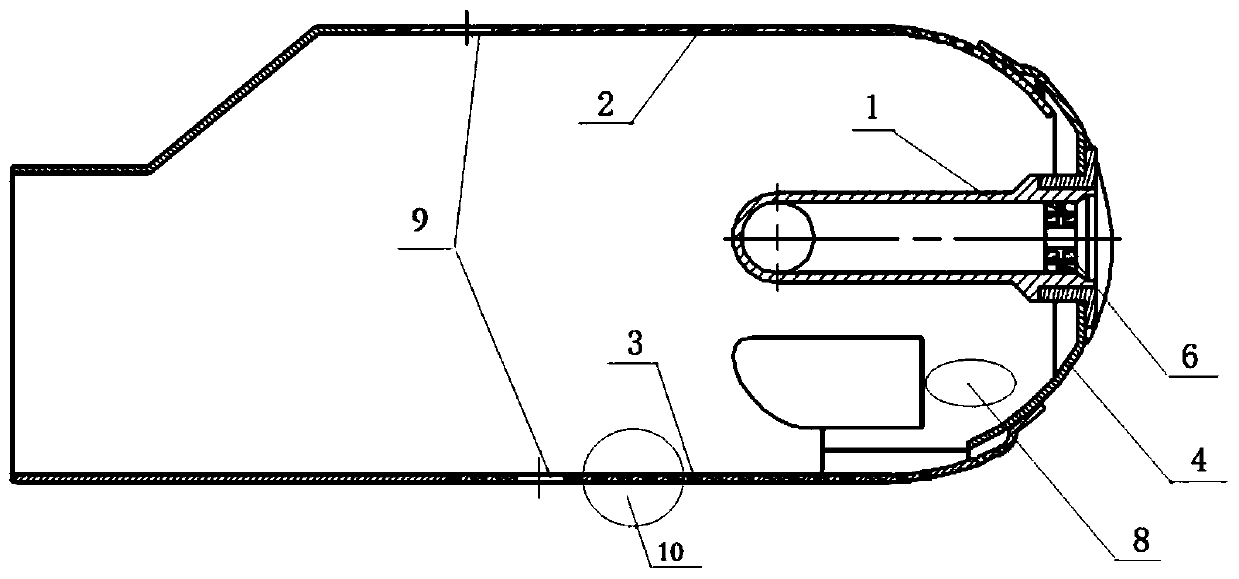
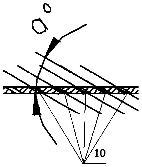
[0029] Such as Figure 1~5 As shown, the evaporating tube combustion chamber of the present invention has a main structure including evaporating tube assembly 1, flame tube outer tube 2, flame tube inner tube 3 and flame tube head 4 and other components, and the components are integrated by welding, wherein The internal area formed between the outer cylinder 2 of the flame cylinder, the inner cylinder 3 of the flame cylinder and the head 4 of the flame cylinder forms a flow field space in the combustion chamber. The evaporating tube assembly 1 at least includes a plurality of evaporating tubes 5 uniformly distributed along the circumference of the flame tube head 4 , and an inlet swirler 6 and an outlet swirler 7 arranged at the inlet and outlet of the ...


PUM


Abstract

The invention provides an evaporating pipe combustion chamber. An inlet and an outlet of an evaporating pipe are each provided with a swirler with a central channel and a swirling flow channel. The swirler at the inlet can speed up breaking, atomizing and evaporating of fuel oil, improve the mixing degree of the fuel oil and air in the evaporating pipe through the initial swirling flow action, andprolong the stay time of an oil-air mixture in the evaporating pipe; the swirler at the outlet enables a low-speed back flowing zone to be formed between the lower portion of the evaporating pipe andthe head of a flame tube through the secondary swirling flow action of the air, and the low-speed back flowing zone is used for improving the flame stability and preventing the condition that the combustion chamber is flamed out in low load. The evaporating pipe combustion chamber is characterized in that the swirling flow action of a swirling flow combustion chamber is applied to the evaporatingpipe combustion chamber, and therefore the double advantages of improving oil-air mixing and improving the combustion stability are achieved. The evaporating pipe combustion chamber can be applied toa micro aircraft engine and a ground gas turbine.

Description

technical field [0001] The invention belongs to the field of aero-engines and gas turbines, and in particular relates to an evaporation tube combustion chamber, which can improve the fragmentation and atomization of fuel oil, promote the mixing of fuel oil and air through two swirling effects, and improve combustion stability and combustion efficiency. Background technique [0002] The evaporating tube structure scheme is widely used in aero-engines and ground gas turbine combustors, especially micro-small power equipment, such as a series of aero-engines such as Turbomeca Arriel in France and AMT in the Netherlands. The combustion chamber adopting the evaporating tube scheme has the advantages of simple structure, easy processing, low cost and good comprehensive combustion performance. It is easy to smoke when it is in a large state, and because there is no special flame stabilizer, the risk of engine flameout is greater when the engine is running below idle or in cruising ...

Claims


Application Information

Patent Timeline
Patent Type & Authority Patents(China)
IPC IPC(8): F23R3/38
CPCF23R3/38
Inventor 刘富强卢海涛穆勇杨金虎刘存喜胡春艳徐纲朱俊强
Owner INST OF ENGINEERING THERMOPHYSICS - CHINESE ACAD OF SCI
Why Eureka
Try Eureka