
Special joint for ground-source heat pump system and ground-source heat pump system

A technology of ground source heat pump and interface, applied in the field of ground source heat pump, can solve the problems of inability to maintain, complicated installation, etc.

Active Publication Date: 2018-02-23
BEIJING TALENT NEW ENERGY TECH DEV CO LTD
View PDF8 Cites 0 Cited by
  • Summary
  • Abstract
  • Description
  • Claims
  • Application Information

AI Technical Summary

Problems solved by technology

[0004] The first purpose of the present invention is to provide a special joint for ground source heat pump system which is simple in structure, reasonable in design, easy to assemble and disassemble, and can conveniently and effectively measure the fluid characteristic data in the buried pipe, so as to solve the existing problems. The traditional temperature measurement method has the problems of cumbersome installation and irreparable repair once damaged
[0005] The second object of the present invention is to provide a ground source heat pump including special joints for ground source heat pump systems with simple structure, reasonable design, easy assembly and disassembly, and the ability to conveniently and effectively measure fluid characteristic data in buried pipes system to solve the problems of cumbersome installation and irreparable repair once damaged in the existing temperature measurement method

Method used


Image

  • Special joint for ground-source heat pump system and ground-source heat pump system
  • Special joint for ground-source heat pump system and ground-source heat pump system

Examples


Embodiment Construction

[0023] In order to make the purpose, technical solutions and advantages of the embodiments of the present invention clearer, the technical solutions in the embodiments of the present invention will be clearly and completely described below in conjunction with the drawings in the embodiments of the present invention. Obviously, the described embodiments It is a part of embodiments of the present invention, but not all embodiments. Based on the embodiments of the present invention, all other embodiments obtained by persons of ordinary skill in the art without making creative efforts belong to the protection scope of the present invention.

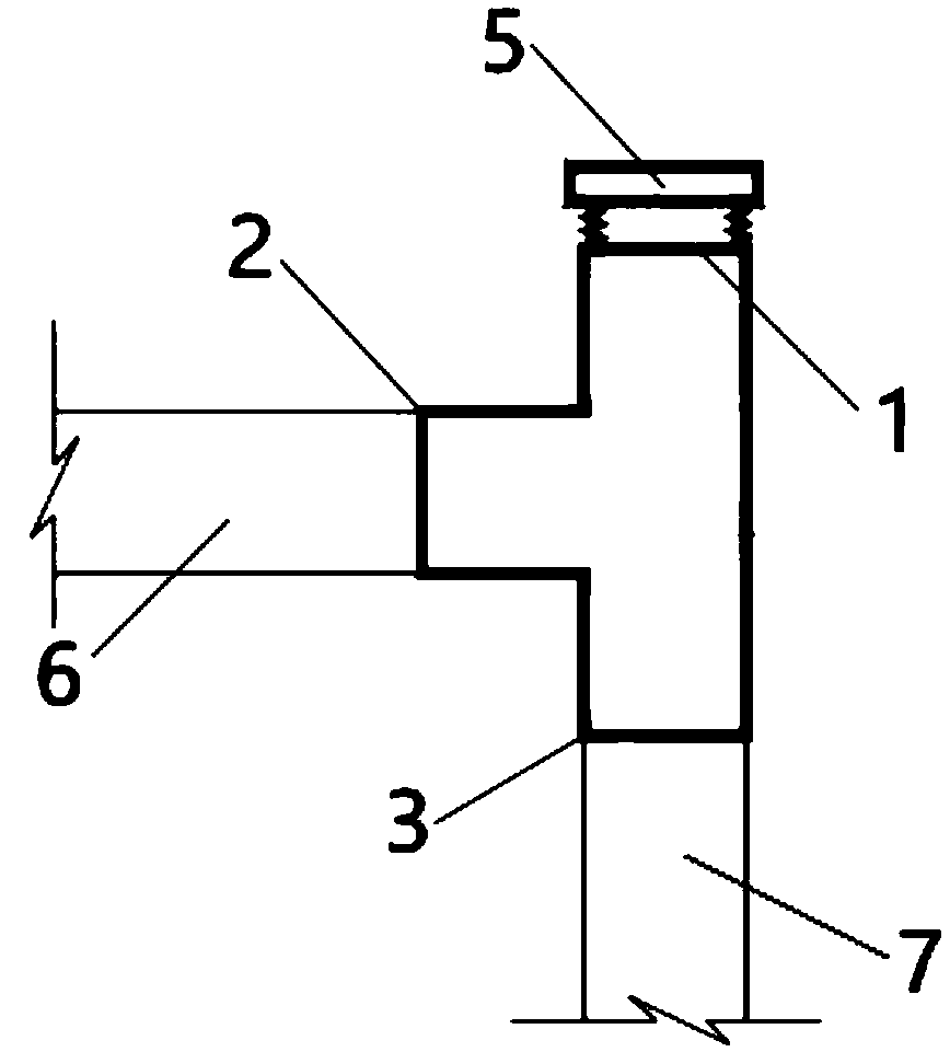
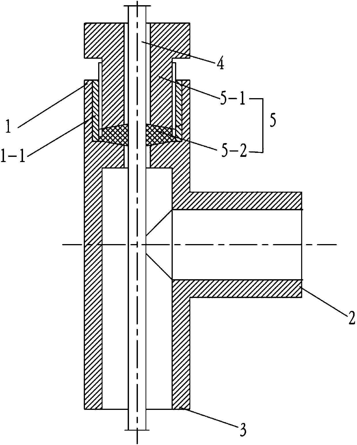
[0024] On the one hand, if Figure 1 to Figure 2 As shown, the embodiment of the present invention provides a special joint for the ground source heat pump system, which includes a vertical joint body with a hollow interior. The joint body includes a first interface 1, a second interface 2 and a third interface. 3, the first interface 1 is s...


PUM


Abstract

The invention relates to the technical field of ground-source heat pumps, in particular to a special joint for a ground-source heat pump system and the ground-source heat pump system. The special joint for the ground-source heat pump system comprises joint body; the joint body is arranged vertically, is hollow inside and comprises a main joint body; the main joint body comprises a first connectingport, a second connecting port and a third connecting port; the first connecting port is arranged at the upper end of the main joint body; the second connecting port is arranged on one side surface of the main joint body; the third connecting port is arranged at the lower end of the main joint body; a tip detachably connected with the first connecting port is arranged at the first connecting portand is provided with a wire hole communicating with an inner cavity of the joint body; a cable of a measuring device penetrates through the wire hole; the second connecting port is connected with a buried pipe horizontal header; and the third connecting port is connected with a buried hole heat exchanger. By the aid of the special joint, characteristic data of a fluid inside a buried pipe can bemeasured conveniently and accurately, design of the buried hole heat exchanger and stable operation of the ground-source heat pump system are effectively guaranteed, and the joint is simple in structure and simple and convenient to mount.

Description

technical field [0001] The invention relates to the technical field of ground source heat pumps, in particular to a special joint for ground source heat pump systems and the ground source heat pump system. Background technique [0002] In recent years, due to the characteristics of environmental protection, high efficiency and energy saving of the ground source heat pump system, with the encouragement and support of the government and relevant departments, the ground source heat pump system has entered a development boom. The core technology of the ground source heat pump air-conditioning system is the design and construction of the buried tube heat exchanger. Since the buried tube heat exchanger is installed underground, it is affected by the difference in soil structure and characteristics at different depths, and it is often difficult to simply calculate it according to the simplified model. If the error is too large, complete and accurate physical parameter data can only...

Claims


Application Information

Patent Timeline
Patent Type & Authority Applications(China)
IPC IPC(8): F25B30/06
CPCF25B30/06Y02E10/10
Inventor 桂江波费群华
Owner BEIJING TALENT NEW ENERGY TECH DEV CO LTD
Learn More