Radio frequency front end circuit and mobile terminal equipment

A radio frequency front-end, mobile terminal technology, applied in the field of communication, can solve the problems of different directivity, low signal-to-noise ratio, weak intensity, etc., and achieve the effect of improving directivity and improving reception quality

Active Publication Date: 2018-02-23
MEIZU TECH CO LTD
View PDF5 Cites 11 Cited by
  • Summary
  • Abstract
  • Description
  • Claims
  • Application Information

AI Technical Summary

Problems solved by technology

[0002] At present, with the popularization of mobile terminal equipment such as mobile phones and the increasingly wide application of positioning information, the requirements for positioning speed and accuracy of satellite positioning systems in complex scenarios are also getting higher and higher. The strength and quality of the GPS (Global Position System, Global Positioning System) signal received by the front-end RF path poses challenges
[0003] GPS satellite signals are characterized by weak strength, low signal-to-noise ratio, and multipath effects. The receiver is sensitive to signal loss and noise. When the antenna directionality is not good, it is easy to cause the strength and signal-to-noise ratio of GPS signals to fluctuate. A drop of several dB, which has a great impact on the positioning quality
[0004] Existing mobile terminal equipment usually only has one GPS antenna, and ...

Method used


Image

  • Radio frequency front end circuit and mobile terminal equipment
  • Radio frequency front end circuit and mobile terminal equipment
  • Radio frequency front end circuit and mobile terminal equipment

Examples


Embodiment Construction

[0030] In order to have a clearer understanding of the above objects, features and advantages of the present invention, the present invention will be further described in detail below in conjunction with the accompanying drawings and specific embodiments. It should be noted that, in the case of no conflict, the embodiments of the present application and the features in the embodiments can be combined with each other.

[0031] In the following description, many specific details are set forth in order to fully understand the present invention. However, the present invention can also be implemented in other ways different from those described here. Therefore, the protection scope of the present invention is not limited by the specific details disclosed below. EXAMPLE LIMITATIONS.

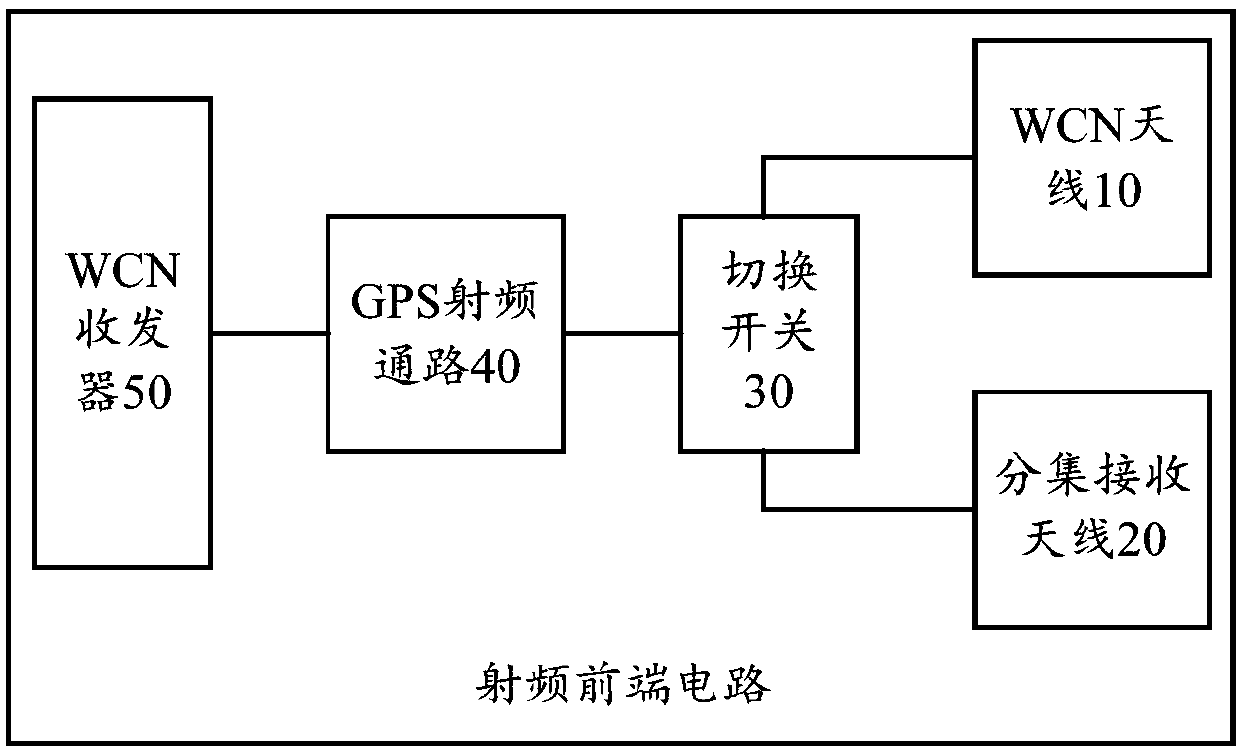
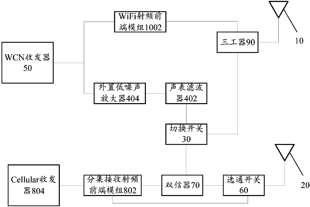
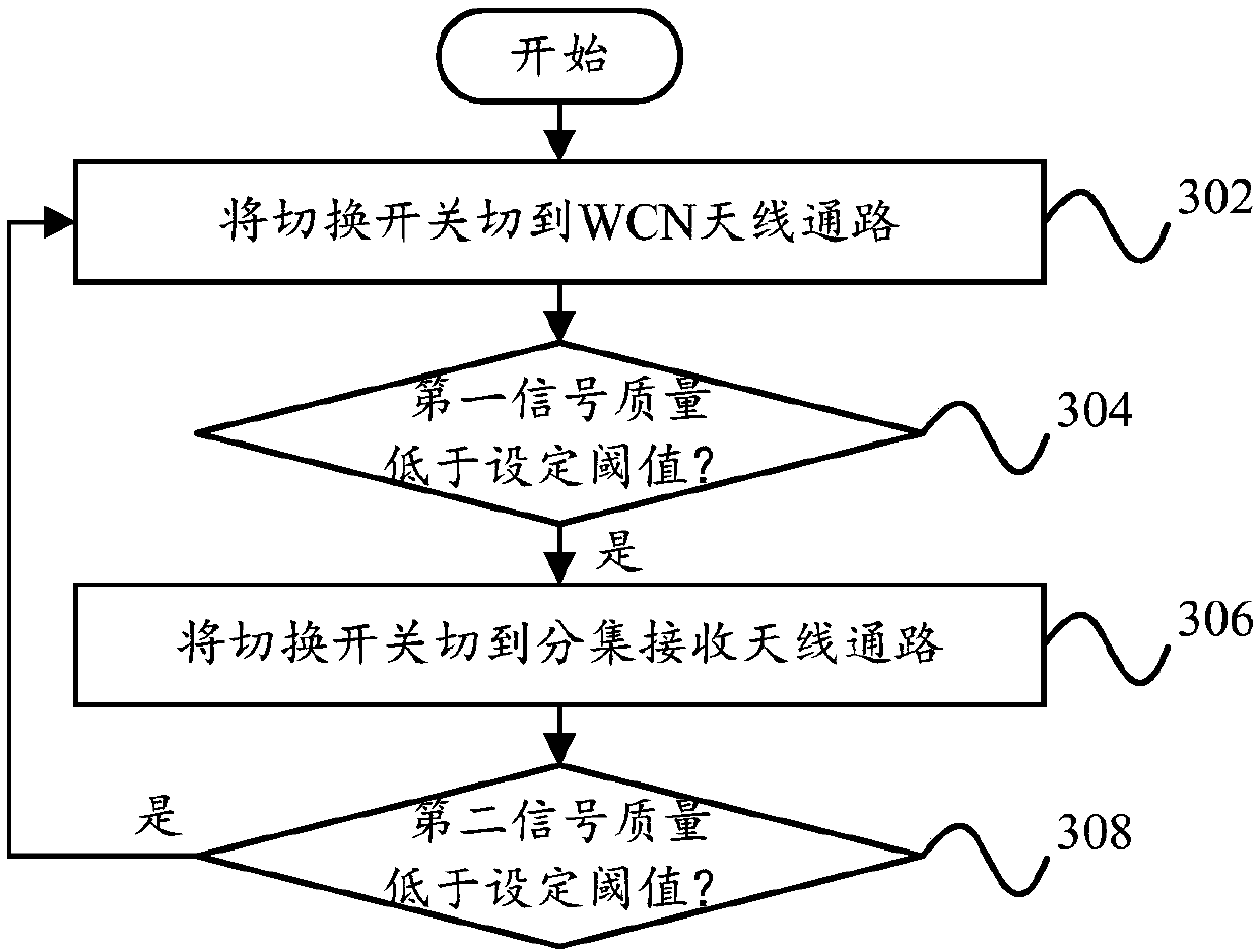
[0032] Combine below Figure 1 to Figure 3 The radio frequency front-end circuit of the embodiment of the present invention will be described in detail.

[0033] Such asfigure 1 As shown, the radio f...


PUM


Abstract

The invention provides a radio frequency front end circuit and mobile terminal equipment. The radio frequency front end circuit comprises a WCN antenna, a diversity reception antenna, a GPS radio frequency path, a WCN transceiver and a selector switch, wherein the WCN antenna is connected with the first end of the selector switch, the diversity reception antenna is connected with the second end ofthe selector switch, and the WCN transceiver is connected with the third end of the selector switch via the GPS radio frequency path; and when a GPS positioning function of the mobile terminal equipment is opened, the WCN antenna is used for receiving GPS signal when the selector switch is changed to be connected with the WCN antenna, and the diversity reception antenna is used for receiving theGPS signals when the selector switch is changed to be connected with the diversity reception antenna, the received GPS signals are transmitted to the WCN transceiver via the GPS radio frequency path.According to the technical scheme, the diversity reception antenna of the mobile terminal equipment is reused for receiving the GPS signals, so that the directionality of the GPS signals is effectively improved, and thus the reception quality of the GPS signals is improved.

Description

technical field [0001] The present invention relates to the technical field of communication, in particular, to a radio frequency front-end circuit and a mobile terminal device. Background technique [0002] At present, with the popularization of mobile terminal equipment such as mobile phones and the increasingly wide application of positioning information, the requirements for positioning speed and accuracy of satellite positioning systems in complex scenarios are also getting higher and higher. The strength and quality of the GPS (Global Position System, Global Positioning System) signal received by the front-end radio frequency path pose challenges. [0003] GPS satellite signals are characterized by weak strength, low signal-to-noise ratio, and multipath effects. The receiver is sensitive to signal loss and noise. When the antenna directionality is not good, it is easy to cause the strength and signal-to-noise ratio of GPS signals to fluctuate. A drop of several dB wil...

Claims


Application Information

Patent Timeline
IPC IPC(8): H04B1/00H04B1/10H04B1/525H04B7/08
CPCH04B1/006H04B1/1027H04B1/525H04B7/0825H04B2001/1045
Inventor 王际玮
Owner MEIZU TECH CO LTD
Why Eureka
Try Eureka