
Jigs for Flange Shaping

A flange and fixture technology, which is applied in the direction of gear teeth, gear cutting machines, manufacturing tools, etc., can solve the problems of easy movement of the flange plate and few fixed limit positions, so as to achieve fixed and stable, not easy to move or deviate moving effect

Active Publication Date: 2019-01-08
重庆市乐珐机电有限责任公司
View PDF8 Cites 2 Cited by
  • Summary
  • Abstract
  • Description
  • Claims
  • Application Information

AI Technical Summary

Problems solved by technology

[0004] The above scheme solves the deficiencies in the prior art through the setting of the positioning plate, but the above scheme still has the following problems: the above scheme only fixes the side of the flange plate through the pressing block, and there are few fixed limit positions. During the gear shaping operation, the flange is still prone to movement

Method used


Image

  • Jigs for Flange Shaping
  • Jigs for Flange Shaping

Examples


Embodiment Construction

[0017] The present invention will be described in further detail below by means of specific embodiments:

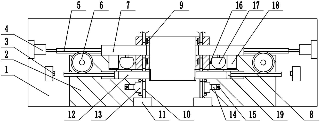
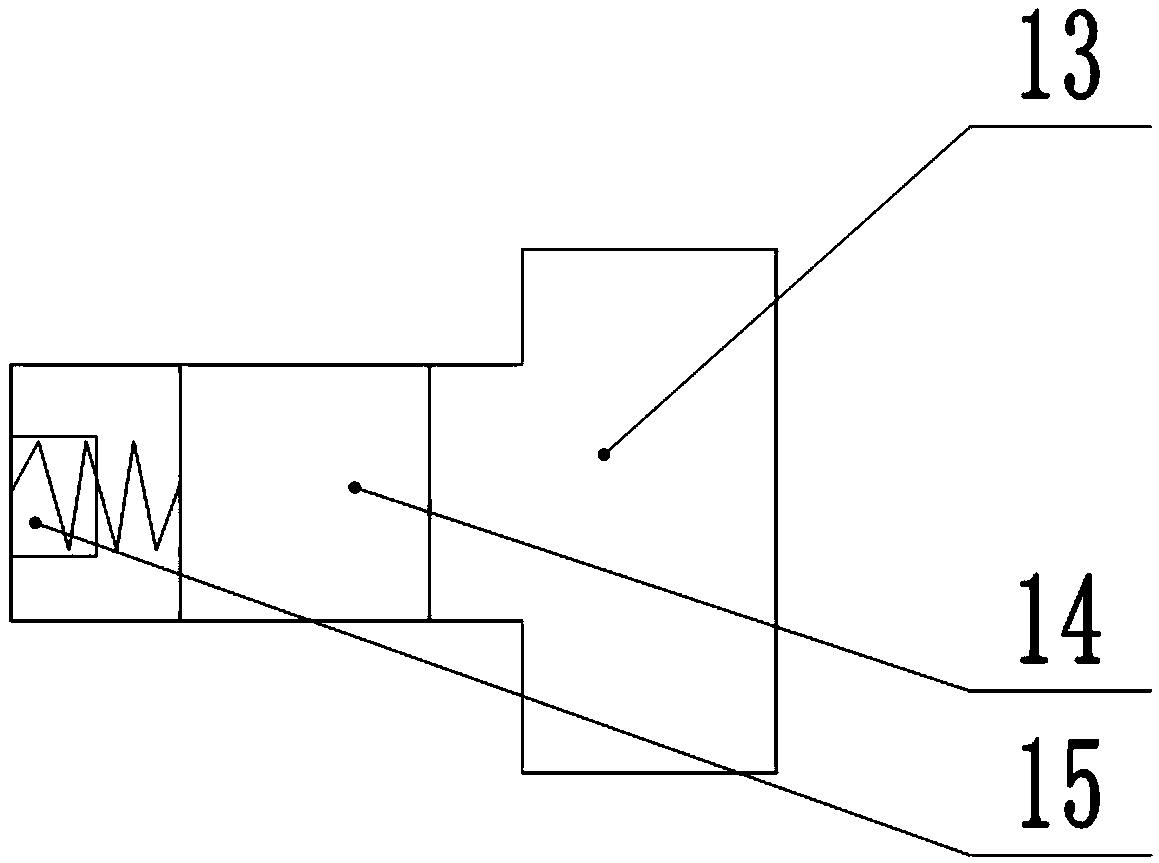
[0018] The reference signs in the drawings of the description include: frame 1, positioning plate 2, third button 3, cylinder 4, first rack 5, gear 6, pressing rod 7, second rack 8, electric heating wire 9 , cold air channel 10, air supply box 11, negative pressure channel 12, water storage tank 13, first piston 14, second button 15, first button 16, water bag 17, pressure plate 18, second piston 19.

[0019] Example basic reference figure 1 and figure 2 Shown: The jig for flange gear shaping includes frame 1, on which frame 1 is welded with positioning disc 2, on which positioning disc 2 is provided with positioning grooves, and on positioning disc 2, there are two pressure plates symmetrical to the center of the positioning slots. The compression device includes a compression rod 7 for compressing the flange, and a cylinder 4 for driving the compression rod 7 to slid...


PUM


Abstract

The invention relates to a clamp used for flange gear shaping. The clamp comprises a rack; a positioning disc is arranged on the rack, a positioning groove is formed in the positioning disc, and the positioning disc is provided with two pressing devices; each pressing device comprises a pressing rod, the pressing rods are slidably connected to the positioning disc, cold air supplying boxes are fixed to the positioning disc, cold air channels are formed in the positioning disc, and the cold air supplying boxes communicate with the cold air channels; pressing plates are fixedly connected to thepressing rods, water bags are fixed to the positioning disc, first buttons are mounted on the wall of the positioning disc, water spraying holes are formed in the pressing rods, and hoses communicatewith the positions between the water bags and the water spraying holes; water storage tanks are formed in the positioning disc, and heating devices are arranged on the outer walls of the water storagetanks and the outer walls of the cold air channels correspondingly; first pistons are slidably connected to the interiors of the water storage tanks, and springs are connected to the positions between the first pistons and the walls of the water storage tanks; and second buttons are mounted on the walls of the water storage tanks. Compared with the prior art, according to the scheme, the functionof multimode fixing of a flange plate through the clamp is achieved by arranging the pressing devices, and fixing of the flange plate is stable.

Description

technical field [0001] The invention relates to the field of positioning and clamping devices, in particular to a clamp for flange gear insertion. Background technique [0002] In the process of inserting the internal teeth of the existing flange plate, the flange plate moves due to the large inserting force, which leads to the phenomenon of disordered teeth. During the clamping process of the flange plate, it takes a long time to find the alignment There are many disadvantages such as affecting work efficiency, low processing quality, inconvenient installation and disassembly, and poor stability of the flange during the slotting process. [0003] In order to solve the above problems, the utility model patent with the Chinese patent application No. 201520080691.0 discloses a flange gear insertion positioning device, which includes a positioning plate, and the upper part of the positioning plate is provided with a positioning stop; the flange is placed on the positioning stop...

Claims


Application Information

Patent Timeline
Patent Type & Authority Patents(China)
IPC IPC(8): B23F23/06B23F23/00
CPCB23F23/00B23F23/06
Inventor 印承霜
Owner 重庆市乐珐机电有限责任公司
Learn More