Driving mechanism

A technology of drive mechanism and transmission mechanism, applied in electromechanical devices, electric components, control of mechanical energy, etc., can solve problems such as small output torque

Inactive Publication Date: 2018-02-27
SHENZHEN ADVANCED TECH CO LTD
View PDF4 Cites 0 Cited by
  • Summary
  • Abstract
  • Description
  • Claims
  • Application Information

AI Technical Summary

Problems solved by technology

[0004] The purpose of the present invention is to provide a driving mechanism to solve the technical problem that the output torque

Method used


Image

  • Driving mechanism
  • Driving mechanism

Examples


Embodiment Construction

[0019] The specific implementation manners of the present invention will be further described in detail below in conjunction with the accompanying drawings and embodiments. The following examples are used to illustrate the present invention, but are not intended to limit the scope of the present invention.

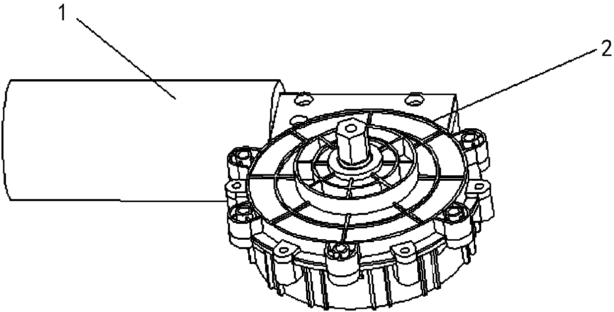
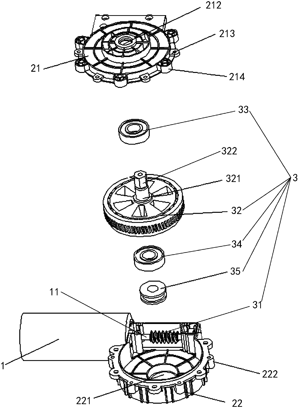
[0020] combine figure 1 with figure 2 As shown, a driving mechanism in a preferred embodiment of the present invention includes a driving device 1 and a housing 2, the driving device 1 is connected to the housing 2, and the driving device 1 has a first output shaft 11; The drive mechanism also includes a transmission mechanism 3, the transmission mechanism 3 is accommodated in the housing 2; the transmission mechanism 3 includes a worm 31 and a turbine 32, and the worm 31 is fixedly connected to the first output shaft 11 Above, the worm 31 meshes with the turbine 32 , the turbine 32 has a second output shaft 321 , and the turbine 32 is rotatably connected in the housing...


PUM


Abstract

The invention relates to the technical field of driving, and discloses a driving mechanism. A transmission mechanism comprises a worm and a turbine, the worm is fixedly connected to a first output shaft of the driving device, the turbine is engaged with the worm, a second output shaft is arranged on the turbine, and the turbine is rotatably connected in a shell through the second output shaft. Theworm is fixedly connected with the first output shaft, and the turbine is engaged with the worm, so that the worm is driven to rotate through rotation of the first output shaft, the turbine is finally driven to rotate, large torque output of the second output shaft is achieved, it is further ensured that the driving mechanism has large output torque, and an automatic cooker with the driving mechanism has a good stir-frying effect.

Description

technical field [0001] The invention relates to the technical field of driving, in particular to a driving mechanism. Background technique [0002] With the advancement of science and technology and the improvement of people's pursuit of living standards, a large number of smart products that optimize life have emerged. As a modern technology product, automatic cooking machines can realize automated cooking processes, so they have fundamentally changed people's food concepts. and lifestyle, thus making its market bigger and bigger. [0003] Existing automatic cooking machines generally use a motor to drive the wok to rotate to achieve the purpose of stir-frying; in order to achieve a sufficient stir-frying effect, the motor of the existing automatic cooking machine is required to have a relatively large output torque. However, because the output torque of the motor of the existing cooking machine is generally small, the motor cannot meet the stir-frying requirements, result...

Claims


Application Information

Patent Timeline
IPC IPC(8): H02K7/116
CPCH02K7/1166
Inventor 许锦标何光
Owner SHENZHEN ADVANCED TECH CO LTD
Why Eureka
Try Eureka