Electric riveting tool

A technology of electric tools and rivets, applied in the field of machinery, can solve the problems of small gear design, limited space usage, and inability to pull off, and achieve the effects of slowing down the riveting speed, enhancing the discharge effect, and accelerating the riveting speed.

Active Publication Date: 2015-03-25
昆山铆足劲工具有限公司
View PDF7 Cites 15 Cited by
  • Summary
  • Abstract
  • Description
  • Claims
  • Application Information

AI Technical Summary

Problems solved by technology

[0005] 1. The meshing teeth of the motor meshing with the motor teeth cannot be made very large, and cannot exceed the axis of the riveting and the waste nail rod discharge, otherwise the waste nail rod cannot be discharged, so the number of teeth and the modulus of the gear are greatly limited, and can only be limited to within a very small range;
[0006] 2. The motor meshes with the motor meshing teeth without interfering and wasting space as much as possible. Therefore, the size of the motor is limited. The speed and power of the motor are closely related to its size. Make it bigger, as the power increases, the motor shaft will also be bigger, and the motor teeth must also be bigger, otherwise it will not be able to mesh, and the reduction ratio will be affected after the motor teeth are bigger
Therefore, it is difficult to freely choose a suitable matching motor in this design;
[0007] 3. The screw nut parts are reprocessed with gears outside the nut. The process is extremely complicated and the requirements are high. The key defect is that if the gear design of the screw nut is too large, the space will be wasted, and the gear design is too small to meet the meshing conditions; To sum up, in the design of this tool, the speed of the motor, the reduction ratio of the reduction gear, and the size of the screw rod cannot be designed according to the needs. It is often a large horse-drawn cart with a slow speed, or a small horse-drawn cart. The car cannot be pulled, and the current electric riveting tools cannot break rivets with strong riveting strength such as ring groove rivets;
[0008] 4. The coordination requirements of the motor assembly, gear, and screw assembly are high. It is necessary to ensure that the three axes are on the same plane while ensuring that the three are parallel. A slight deviation in parallelism and flatness will affect the meshing requirements, resulting in tools. noisy
[0009] (2) In terms of appearance design, for the smooth discharge of the nail rod, the arrangement of the accessories is limited to parallel arrangement. For example, the motor must be placed in the direction parallel to the direction of the screw rod, which greatly restricts the use of space, resulting in a large Waste of space, bloated tool shape, the center of gravity of the handheld cannot meet the needs of human mechanics, there is no good point of contact for handshake, and the user is prone to fatigue. It is difficult to change this inhumane mechanism layout under the existing conditions

Method used


Image

  • Electric riveting tool
  • Electric riveting tool
  • Electric riveting tool

Examples


Embodiment Construction

[0037] The present invention will be further described below in conjunction with accompanying drawing;

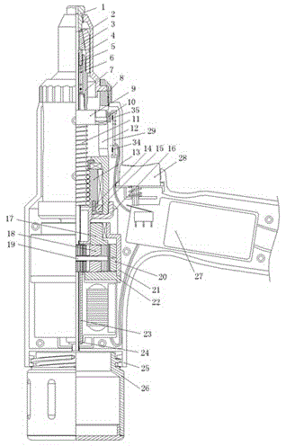
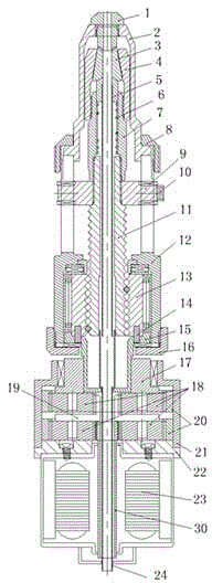
[0038] Such as figure 1 , figure 2 , image 3 , Figure 4 , Figure 5 and Figure 6 As shown, the rivet power tool includes an outer cover 25, a trigger 28, a circuit board 27, a nail collection tube 26, a riveting system, a screw drive system, a planetary gear reduction system and a power motor assembly;

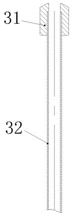
[0039] Such as figure 1 and figure 2 As shown, the screw drive system includes a roller positioning block 9, a ball screw 11, a screw nut 13, a front bearing seat 12, a rear bearing seat 16, and a connecting shaft 15, and the ball screw 11 is a hollow structure. It passes through the core pipe 32 and is used for the ejector rod. The front end is fixed by the roller positioning block 9, and the rear end is connected with the screw nut 13. The screw nut 13 is arranged in the front bearing seat 12; the rear bearing seat 16 and The front bearing block 12 is co...


PUM


Abstract

The invention relates to an electric riveting tool used in the technical field of machines. The tool is composed of an outer cover, a trigger, a rivet pulling system, a lead screw transmission system, a planetary gear speed-reducing system and a power motor assembly. A spring sleeve is connected with the front end of a ball lead screw, the planetary gear speed-reducing system is fixed to a lead screw nut through a connection shaft, the power motor assembly is connected with the planetary gear speed-reducing system, a nail collecting cylinder is arranged at the rear end of the power motor assembly, a discharging pipe penetrates through a motor shaft and the planetary gear speed-reducing system and then is arranged outside a core ejector pipe in a sleeving mode, the outer cover is provided with a circuit board, the trigger and a stroke control plate, the circuit board is connected with a motor and the stroke control plate through control lines, the stroke control plate is provided with an inductor, a rolling wheel positioning block is provided with a magnet, and the inductor is located on the lower portion of the magnet. The tool is strong in power, can be used for work indoors and outdoors, is used in a handheld mode, accords with the principle of ergonomics, makes full use of tool space, can be used for pulling rivets of different specifications and is high in applicability, and waste nail rod discharging is easy.

Description

technical field [0001] The invention belongs to the technical field of machinery, and in particular relates to an electric riveting tool. Background technique [0002] Rivet tool is a tool specially used for rivet installation, including pneumatic rivet gun and electric rivet gun. Pneumatic rivet tool has the advantages of fast speed and large pulling force, but its rigid requirement is that it must have an air source and an air pipe when using it. Connected to the air source, the noise is loud when riveting. Although the riveting force can be made larger, the volume will also increase, especially in the field. Because the electric rivet gun has a hand-held power supply, it can be operated in the field. It is widely used, but the electric rivet gun has the following limitations, which brings great inconvenience to the operator. [0003] There are two ways for the electric rivet tool to discharge the waste nail rod after being pulled out. One is to eject the nail from the fr...

Claims


Application Information

Patent Timeline
Patent Type & Authority Applications(China)
IPC IPC(8): B21J15/38F16H37/02F16H1/32F16H25/22
CPCB21J15/383F16H37/02F16H2702/00B21J15/043B21J15/105B21J15/26B21J15/326
Inventor 洪劲松
Owner 昆山铆足劲工具有限公司
Why Eureka
Try Eureka