Agricultural monitoring device based on Internet of Things

A monitoring device and the technology of the Internet of Things, which are applied in the fields of capturing or killing insects, measuring devices, animal husbandry, etc., can solve the problems of inaccurate data collection, low efficiency, inaccurate monitoring data, etc. High efficiency and easy operation effect

Inactive Publication Date: 2018-02-27
JINLING INST OF TECH
4 Cites 2 Cited by

AI-Extracted Technical Summary

Problems solved by technology

[0002] The existing agricultural monitoring devices based on the Internet of Things are basically mature in technology, and they are all realized through the Internet of Things server, display t...

Method used

[0013] In order to make the purpose of the present invention, technical solutions and advantages more clear, the following describes the present invention by specific embodiments shown in the accompanying drawings. It should be understood, however, that these desc...

Abstract

The invention discloses an agricultural monitoring device based on the Internet of Things, and relates to the technical field of agricultural monitoring. An Internet of Things server is connected witha display terminal, the Internet of Things server is separately connected with a temperature and humidity detection sensor, a camera collection device and an insect collection device, a rotating motor is installed on a lifting rod of an electric lifter, a high definition camera is installed on the rotating shaft of the rotating motor, a controller is installed on the side wall of the electric lifter, an input end of the controller is connected with the high definition camera, an output end of the controller is connected with the rotating motor and the electric lifter separately, a V-shaped inlet pipe is installed on the top left end of a collection cylinder, a detection head is installed on the upper end of the collection cylinder, an insect inducer is installed on the inner lower side ofthe collection cylinder, a GPS positioning module is installed at the bottom in the collection cylinder, and a shooting camera is installed on the side wall of the collection cylinder via a bracket.The agricultural monitoring device disclosed by the invention can conveniently achieve accurate data collection, and is adjustable, convenient to use, simple and convenient to operate, and high in efficiency.

Application Domain

Technology Topic

Image

  • Agricultural monitoring device based on Internet of Things

Examples

  • Experimental program(1)

Example Embodiment

[0013] In order to make the objectives, technical solutions, and advantages of the present invention clearer, the following describes the present invention through specific embodiments shown in the drawings. However, it should be understood that these descriptions are only exemplary and not intended to limit the scope of the present invention. In addition, in the following description, descriptions of well-known structures and technologies are omitted to avoid unnecessarily obscuring the concept of the present invention.
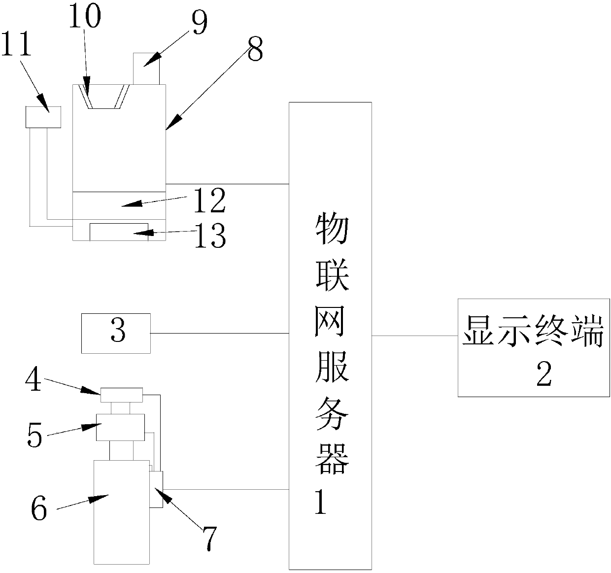
[0014] Such as figure 1 As shown, this specific embodiment adopts the following technical solutions: it includes an Internet of Things server 1, a display terminal 2, a temperature and humidity detection sensor 3, a camera collection device and an insect collection device, the Internet of Things server 1 is connected to the display terminal 2, and the thing The networked server 1 is respectively connected with a temperature and humidity detection sensor 3, a camera collection device, and an insect collection device, and is characterized in that: the camera collection device includes a high-definition camera 4, a rotating motor 5, an electric descender 6, and a controller 7; A rotating motor 5 is installed on the lifting rod of the electric lifter 6, a high-definition camera 4 is installed on the shaft of the rotating motor 5, a controller 7 is installed on the side wall of the electric lifter 6, and the input end of the controller 7 and the high-definition camera 4 The output ends of the controller 7 are respectively connected to the rotating motor 5 and the electric extension device 6. The insect collecting device includes a collecting tube 8, a probe 9, a V-shaped inlet tube 10, a shooting camera 11, an insect inducer 12, GPS positioning module 13; the upper left end of the collection tube 8 is equipped with a V-shaped inlet tube 10, the upper end of the collection tube 9 is installed with a probe 9, the inner and lower side of the collection tube 8 is installed with an insect inducer 12, and the inner bottom of the collection tube 9 A GPS positioning module 13 is installed, and a shooting camera 11 is installed on the side wall of the collecting tube 8 through a bracket.
[0015] Further, the insect inducer 12 is equipped with an induction liquid inside.
[0016] Further, the rotating electric machine 5 and the electric descender 6 are all waterproof.
[0017] Further, the collection cylinder 8 is a transparent collection cylinder.
[0018] Further, the detection head 9 is an infrared detection head.
[0019] The working principle of this embodiment is: when in use, data is received, sent, and displayed through the Internet of Things server 1 and the display terminal 2, and the data is collected through the temperature and humidity detection sensor 3, camera collection device and insect collection device , The temperature and humidity detection sensor 3 realizes the detection of temperature and humidity, and at the same time, it detects the pictures of plant roots, stems and leaves when the camera acquisition device is adjusted. It adjusts the height and angle of the high-definition camera through a rotating motor and an electric descender. The operation is simple and convenient. At the same time, the collection of insects is achieved through the collection tube 8, and the induction of insects is achieved through the insect inducer, so that the insects enter the collection tube from the V-shaped inlet tube 10, and the GPS positioning module realizes the positioning of the collection tube, and the shooting camera 11 It can realize the shooting of insects, which is convenient for data collection.
[0020] In the description of the present invention, unless otherwise clearly specified and limited, the terms "installation", "connected", "connected", and "fixed" should be interpreted broadly, for example, it may be a fixed connection or a detachable connection , Or integrated; it can be a mechanical connection or an electrical connection; it can be directly connected or indirectly connected through an intermediate medium, and it can be the internal communication of two components or the interaction relationship between two components. For those of ordinary skill in the art, the specific meaning of the above-mentioned terms in the present invention can be understood in specific situations.
[0021] The standard parts used in the present invention can be purchased from the market, the special-shaped parts can be customized according to the description in the manual and the drawings, and the specific connection methods of each part adopt the mature bolts, rivets, welding, etc. in the prior art Conventional means, machinery, parts and equipment adopt the conventional models in the prior art, and the circuit connection adopts the conventional connection methods in the prior art, which will not be detailed here.
[0022] For those skilled in the art, it is obvious that the present invention is not limited to the details of the above exemplary embodiments, and the present invention can be implemented in other specific forms without departing from the spirit or basic characteristics of the present invention. Therefore, from any point of view, the embodiments should be regarded as exemplary and non-limiting. The scope of the present invention is defined by the appended claims rather than the above description, and therefore it is intended to fall within the claims. All changes within the meaning and scope of the equivalent elements of are included in the present invention. Any reference signs in the claims should not be regarded as limiting the claims involved.
[0023] In addition, it should be understood that although this specification is described in accordance with the implementation manners, not each implementation manner only contains an independent technical solution. This narration in the specification is only for clarity, and those skilled in the art should regard the specification as a whole The technical solutions in the embodiments can also be appropriately combined to form other implementations that can be understood by those skilled in the art.

PUM

no PUM

Description & Claims & Application Information

We can also present the details of the Description, Claims and Application information to help users get a comprehensive understanding of the technical details of the patent, such as background art, summary of invention, brief description of drawings, description of embodiments, and other original content. On the other hand, users can also determine the specific scope of protection of the technology through the list of claims; as well as understand the changes in the life cycle of the technology with the presentation of the patent timeline. Login to view more.

Similar technology patents

Heater assembly

Owner:FOSHAN VIOMI ELECTRICAL TECH +1

Classification and recommendation of technical efficacy words

  • Achieve regulation
  • Accurate collection

Load positioning device for structural test

InactiveCN102809508AAchieve regulationSimple and convenient adjustment stepsStrength propertiesLocknutEngineering
Owner:SHANGHAI JIAO TONG UNIV
Why Eureka
Try Eureka