Roller drive

A technology for rollers, drive systems, applied in electric components, asynchronous induction motors, transportation and packaging, etc., can solve problems such as limiting the size of internal motors

Inactive Publication Date: 2018-02-27
LAITRAM LLC
View PDF0 Cites 0 Cited by
  • Summary
  • Abstract
  • Description
  • Claims
  • Application Information

AI Technical Summary

Problems solved by technology

But the small outer diameter of the motorized drum limits the size of the internal motor and the maximum torque available for a given drum speed

Method used


Image

  • Roller drive
  • Roller drive
  • Roller drive

Examples


Embodiment Construction

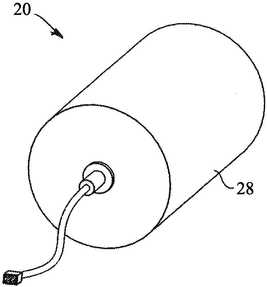
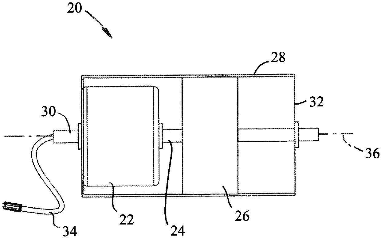
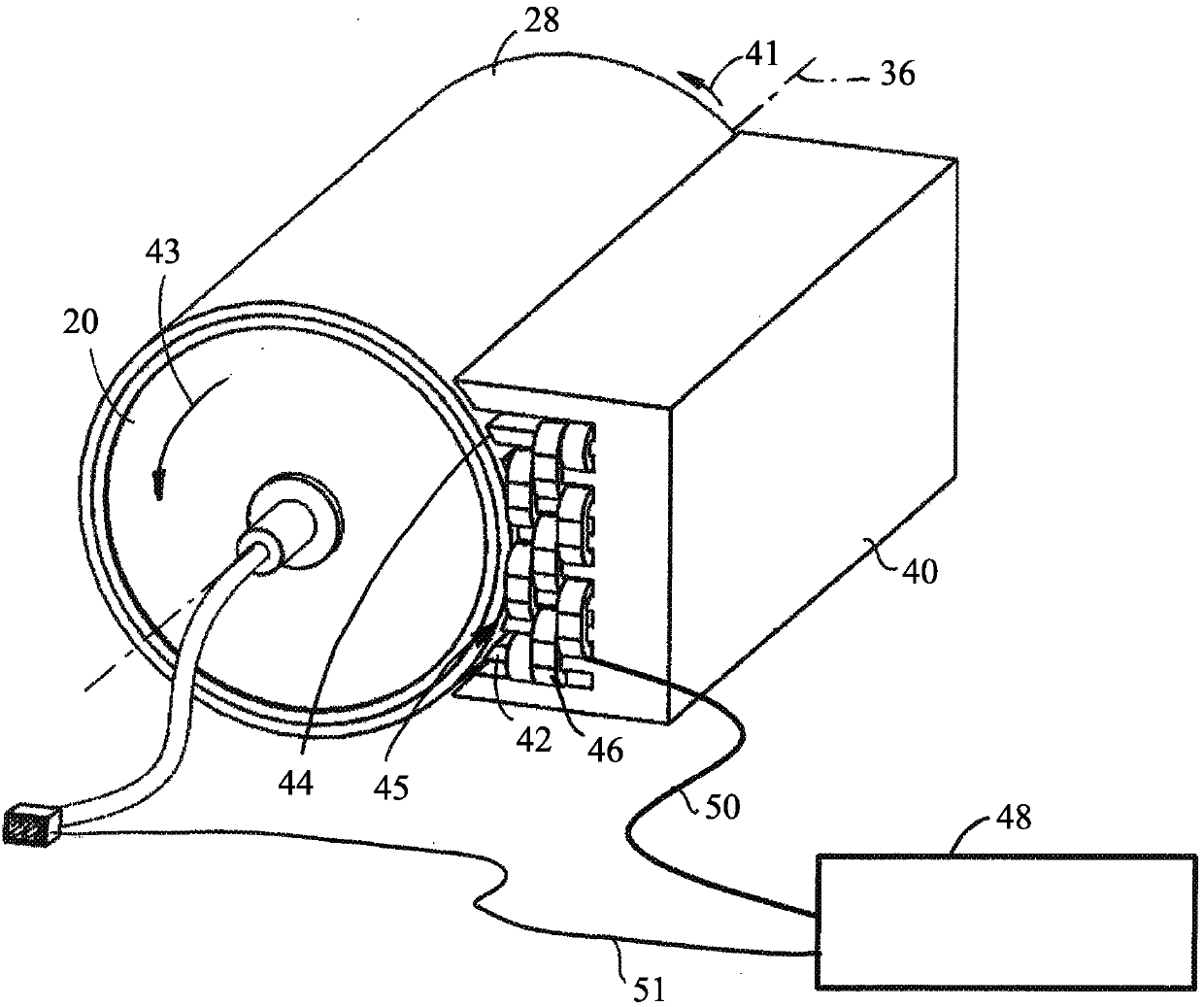
[0019] figure 2 A power assist drive system for a motorized drum embodying features of the present invention is shown in . The stator 40 is positioned close to the cylindrical outer housing 28 of the motorized roller 20 which is stationary mounted at a fixed position in the conveyor frame (not shown). The main drive of the motorized drum is its integrated electric motor. The stator 40 has a pole array 42 terminating in a pole face 44 adjacent the housing 28 . Each pole 42 is surrounded by a winding 46 (eg, a three-phase winding). The pole face 44 defines a curved plane whose shape is complementary to the outer shell 28 of the motorized drum 20 across the air gap 45 . The stator 40 is the source of an external magnetic field positioned proximate to the outer housing 28 .

[0020] The stator 40 extends axially along most of the length of the motorized drum 20 , and circumferentially along only a portion of the cylindrical outer casing 28 . The stator 40 generates flux waves...


PUM


Abstract

A drive system for a motorized roller that includes a secondary stator external to the motorized roller. The outer shell of the motorized roller contains electrically conductive or magnetic material to form an induction, permanent-magnet, or reluctance motor with the secondary stator and boosts or bucks the torque of the motorized roller.

Description

Background technique [0001] The present invention relates to power driven conveyors, and more particularly to motorized rollers. [0002] Motorized rollers are typically used to propel a series of conveyor rollers or conveyor belts. As shown in FIGS. 1 a and 1 b , the motorized drum 20 generally includes an electric motor 22 whose output shaft 24 is coupled to a reduction gear 26 that drives a cylindrical outer housing 28 . The electric motor 22 and the reduction gear 26 are housed inside a hollow cylindrical case 28 . Stationary end shafts 30 extend from end caps 32 for mounting motorized rollers 20 to the side walls of the conveyor. At least one of the stationary shafts 30 may be hollow to permit entry of power and control cables 34 into the motor 22 . The cylindrical outer housing 28 rotates about an axis of rotation 36 which coincides with the shafts 24 , 30 . The housing 28 may directly drive a tensioned conveyor belt; the housing may directly push the items and drive...

Claims


Application Information

Patent Timeline
Patent Type & Authority Applications(China)
IPC IPC(8): H02K41/02B65G23/04B65G23/22
CPCB65G23/04B65G23/22H02K41/02H02K2207/03B65G13/06B65G23/06B65G23/08H02K1/246H02K1/2753H02K7/14H02K17/165H02K19/106
Inventor 布赖恩特·G·拉根约翰·F·兰德拉姆罗伯特·L·罗森
Owner LAITRAM LLC
Why Eureka
Try Eureka