Pressure relief structure for offshore wind turbine

A technology of wind power generator and pressure relief structure, applied in the direction of valve casing structure, engine components, mechanical equipment, etc., can solve the problems of low working efficiency, inconvenience, and inability to complete pressure relief, so as to improve the efficiency of pressure relief and simple operation Effect

Pending Publication Date: 2018-03-02
南通精维风电科技有限公司
View PDF0 Cites 0 Cited by
  • Summary
  • Abstract
  • Description
  • Claims
  • Application Information

AI Technical Summary

Problems solved by technology

[0003] However, the end 21 of the existing pressure relief rod 2 is mostly an inner hexagonal head or an outer hexagonal head or a straight head or a cross head. When it is necessary to relieve pressure, it is necessary to unscrew the pressure relief rod with a special wrench to release the pressure. Sometimes if the operator forgets to bring the special wrench, the pressure relief cannot be completed, which is very inconvenient; and through the threaded connection, the pressure relief cannot be completed quickly, and the work efficiency is low

Method used


Image

  • Pressure relief structure for offshore wind turbine
  • Pressure relief structure for offshore wind turbine
  • Pressure relief structure for offshore wind turbine

Examples


Embodiment approach

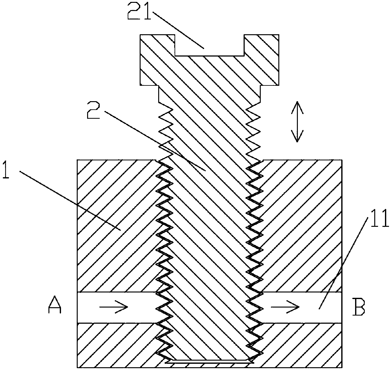
[0034] In order to achieve the purpose of the present invention, as shown in the figure, an embodiment of the present invention is: a pressure relief structure for offshore wind power generators, including:

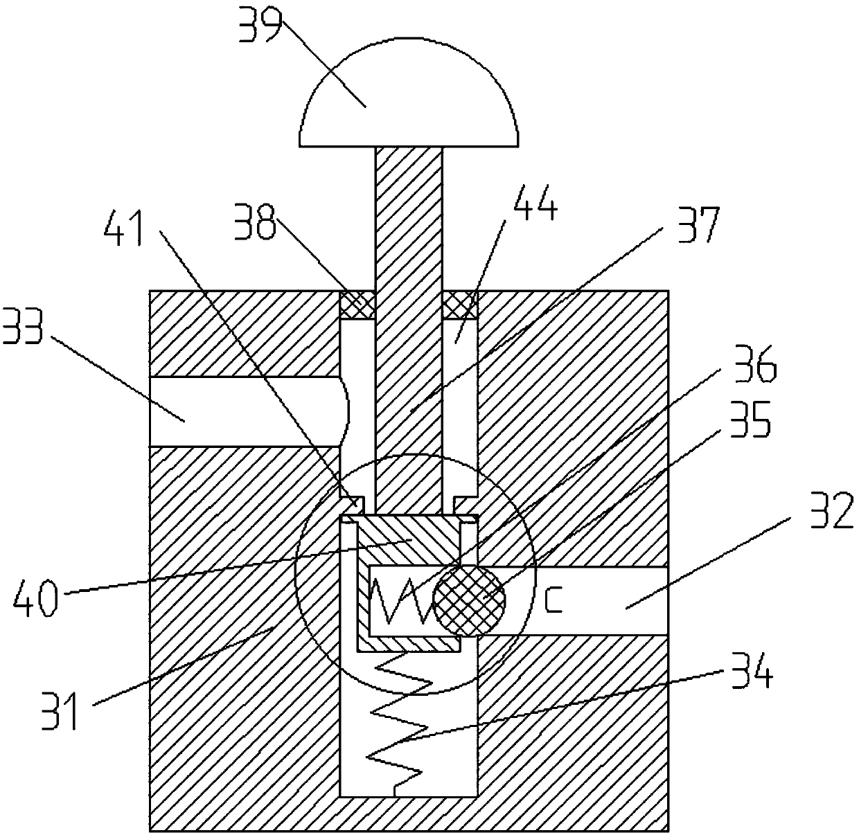
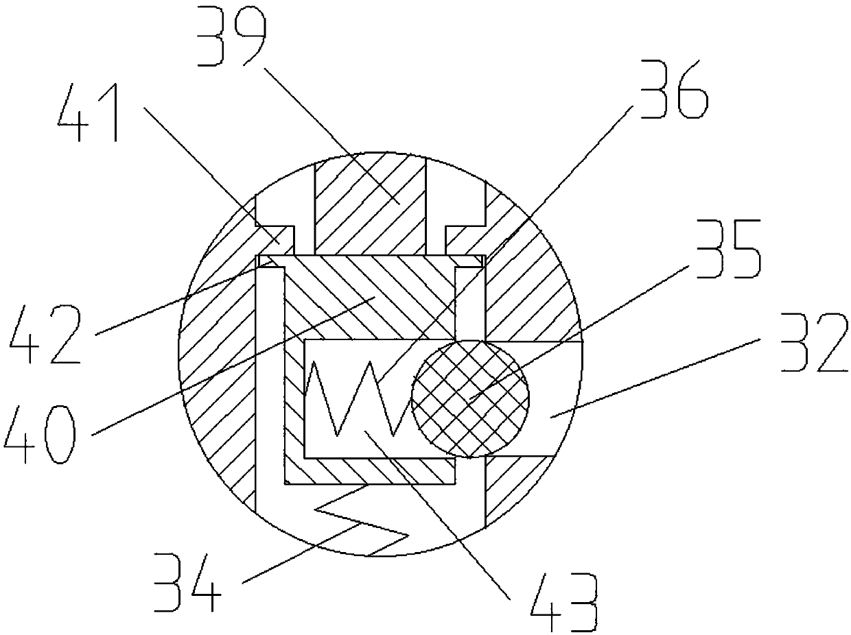
[0035] The valve body 31 has an oil inlet 33 and an oil outlet 32 ​​on both sides of the valve body 31. A blind hole 44 is provided in the middle of the valve body 31. The height of the oil inlet 33 is higher than that of the oil outlet 32. , the normal circulation of the pressure relief passage can be guaranteed, and the backflow phenomenon can be avoided. The oil inlet 33, the blind hole 44 and the oil outlet 32 ​​form a pressure relief passage, and the inner wall of the blind hole 44 is provided with a limit stopper 41. 41 is located between the oil outlet 32 ​​and the oil inlet 33 in the vertical direction;

[0036] Slide bar 37, slide bar 37 moves up and down along the axis of blind hole 44, is provided with T-shaped slide block 40 below slide bar 37, and T-shaped sl...


PUM


Abstract

The invention discloses a pressure relief structure for an offshore wind turbine. The pressure relief structure comprises a valve body, a sliding rod and a sealing cap; an oil inlet and an oil outletare formed in two sides of the valve body; a blind hole is formed in the middle of the valve body; the oil inlet is higher than the oil outlet; and the oil inlet, the blind hole and the oil outlet form a pressure relief passage; the sliding rod moves up and down along the axis of the blind hole; a T-shaped sliding block is arranged below the sliding rod and comprises a baffle part and a vertical part perpendicular to the baffle part; a first spring is arranged in the blind hole; a notch is formed in one side surface of the vertical part of the T-shaped sliding block; a second spring and an ejecting bead are arranged in the notch; the diameter of the ejecting bead is larger than that of the oil outlet; and the sealing gap is arranged on the sliding rod in a sleeving manner and is detachablyconnected with the blind hole. The pressure relief structure has the beneficial effects as follows: the sliding rod moves up and down through pressing, and pressure relief is completed by the aid ofthe pressure relief passage formed by the oil inlet, the blind hole and the oil outlet and can be completed without a special spanner, so that the pressure relief efficiency is greatly improved, and the pressure relief structure is simple to operate.

Description

technical field [0001] The invention relates to the field of offshore wind power generators, in particular to a pressure relief structure for offshore wind power generators. Background technique [0002] Offshore wind turbines mainly convert wind energy into electrical energy, and the hydraulic pitch unit is an important part of seawater wind turbines. At present, the structure of the pressure relief port of the hydraulic pitch unit is as follows: figure 1 As shown, it includes a valve body 1 and a pressure relief rod 2, wherein the valve body 1 is provided with an oil inlet A and an oil outlet B. When the pressure is released, the oil inlet A and the oil outlet B form a pressure relief oil passage 11, The pressure relief rod 2 is threadedly connected with the valve body 1. When the pressure relief is not required, the pressure relief rod 2 will block the pressure relief passage; when the pressure relief is required, turn the pressure relief rod 2 to connect the oil inlet A ...

Claims


Application Information

Patent Timeline
Patent Type & Authority Applications(China)
IPC IPC(8): F16K15/18F16K1/46F16K27/02F16K35/00
CPCF16K1/46F16K27/0209F16K27/0245F16K35/00F16K15/1823
Inventor 秦臻季永圣
Owner 南通精维风电科技有限公司
Why Eureka
Try Eureka