
Transmission shaft vibration test system

A technology of vibration testing and transmission shaft, which is applied in the direction of machine gear/transmission mechanism testing, mechanical bearing testing, mechanical component testing, etc., and can solve problems such as the lack of mature transmission shaft vibration testing technology

Inactive Publication Date: 2018-03-02
SHAANXI EYOUNG TECH
View PDF0 Cites 7 Cited by
  • Summary
  • Abstract
  • Description
  • Claims
  • Application Information

AI Technical Summary

Problems solved by technology

However, there is no relatively mature transmission shaft vibration testing technology

Method used


Image

  • Transmission shaft vibration test system

Examples


Embodiment 1

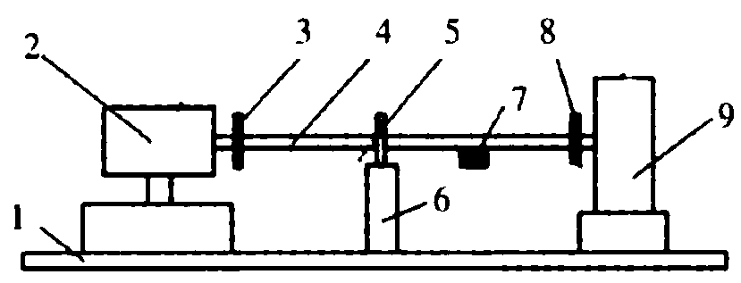
[0013] A transmission shaft vibration testing system according to the present invention includes a test bench, a vibration isolation base 1, a drive motor 2, an input speed sensor 3, a vibration acceleration sensor 5, an intermediate bracket 6, a shaft tube radial displacement sensor 7, an output The end speed sensor 8, the dynamometer 9 and the controller 10, wherein the vibration isolation base 1 and the dynamometer 9 are fixedly arranged on the test bench, and are separately arranged on both sides of the test bench, between the vibration isolation base 1 and the dynamometer 9 A bracket is fixedly installed, and a drive motor 2 is fixedly installed on the upper part of the vibration isolation base 1. The input speed sensor 3 is arranged at one end of the drive motor 2. The input speed sensor 3, the vibration acceleration sensor 5, the shaft tube radial displacement sensor 7, The output speed sensors 8 are connected to the controller 10 respectively.

[0014] The input speed ...


PUM


Abstract

The invention relates to a transmission shaft vibration test system, which includes a test bench, a vibration isolation base, a drive motor, an input speed sensor, a vibration acceleration sensor, an intermediate support, a shaft tube radial displacement sensor, an output speed sensor, and a dynamometer and the controller, wherein the vibration isolation base and the dynamometer are fixedly arranged on the test bench, and are separately arranged on both sides of the test bench, a bracket is fixed between the vibration isolation base and the dynamometer, and a drive is fixed on the upper part of the vibration isolation base. The motor, the speed sensor at the input end is set at one end of the drive motor, the speed sensor at the input end, the vibration acceleration sensor, the radial displacement sensor of the shaft tube, and the speed sensor at the output end are all connected to the controller respectively. The transmission shaft vibration testing system of the present invention can effectively discriminate abnormal sound transmission shafts and non-abnormal sound transmission shafts, so as to realize quality control on the NVH aspect of the transmission shafts.

Description

technical field [0001] The invention relates to a transmission shaft vibration testing system. Background technique [0002] NVH performance has long been one of the most concerned issues for automakers. As the main noise and vibration sources in the car have been better controlled. Some noise or abnormal noise problems of parts that were covered up before were gradually exposed. Among them, the NVH problem in the car caused by the vibration of the transmission shaft has become one of the hot spots of user complaints. [0003] The vibration of the car transmission shaft is closely related to the abnormal noise inside the car. Effective testing of drive shaft vibration characteristics. It is of great significance to the analysis and control of abnormal noise in the car. However, there is no relatively mature transmission shaft vibration testing technology. Contents of the invention [0004] To solve the above technical problems, the present invention proposes a transm...

Claims


Application Information

Patent Timeline
Patent Type & Authority Applications(China)
IPC IPC(8): G01M13/02G01M13/04
CPCG01M13/025G01M13/028G01M13/045
Inventor 张俊
Owner SHAANXI EYOUNG TECH
Learn More