
System and method for corrosion diagnosis of grounding grid of transformer substation on the basis of inductive apparent magnetic impedance method

A substation grounding grid and diagnostic method technology, applied in the direction of material magnetic variables, etc., can solve the problems of inaccurate judgment of corrosion degree and breakpoint, difficult actual operation, heavy workload, etc., to achieve true and reliable diagnostic results and reliable measurement data , the effect of improving work efficiency

Inactive Publication Date: 2018-03-02
STATE GRID CORP OF CHINA +2
View PDF5 Cites 8 Cited by
  • Summary
  • Abstract
  • Description
  • Claims
  • Application Information

AI Technical Summary

Benefits of technology

This patented device described an approach called inductive viscosity (IVR) technique that helps diagnose damage caused by electric arcs or other factors affecting power distribution systems used at different locations around them. It involves applying high voltage AC currents through conductors placed near each location where potential problems may occur due to exposure to these conditions during operation. By analyzing this response from multiple sensory points located close together along one axis, it becomes possible to identify areas affected by any issues related to insulation failure. Overall, IVR provides technical benefits over traditional methods like electrochemistry techniques and visual observation.

Problems solved by technology

Technological Problem: The technical problem addressed in this patented text relates to developing a simplified but effective way to check if there are any areas where corrosive material may be present at or near certain locations within the groundings used for electricity transmission lines (GIL). Current methods rely heavily relying upon laboratory measurements which have limitations such as lack accuracy due to factors like environmental variables affecting their effectiveness, long wait times between testing cycles, and potential damage caused during excavating operations.

Method used


Image

  • System and method for corrosion diagnosis of grounding grid of transformer substation on the basis of inductive apparent magnetic impedance method
  • System and method for corrosion diagnosis of grounding grid of transformer substation on the basis of inductive apparent magnetic impedance method
  • System and method for corrosion diagnosis of grounding grid of transformer substation on the basis of inductive apparent magnetic impedance method

Examples


Embodiment Construction

[0024] In order to have a clearer understanding of the technical features, purposes and effects of the present invention, the specific implementation manners of the present invention will now be described in detail with reference to the accompanying drawings.

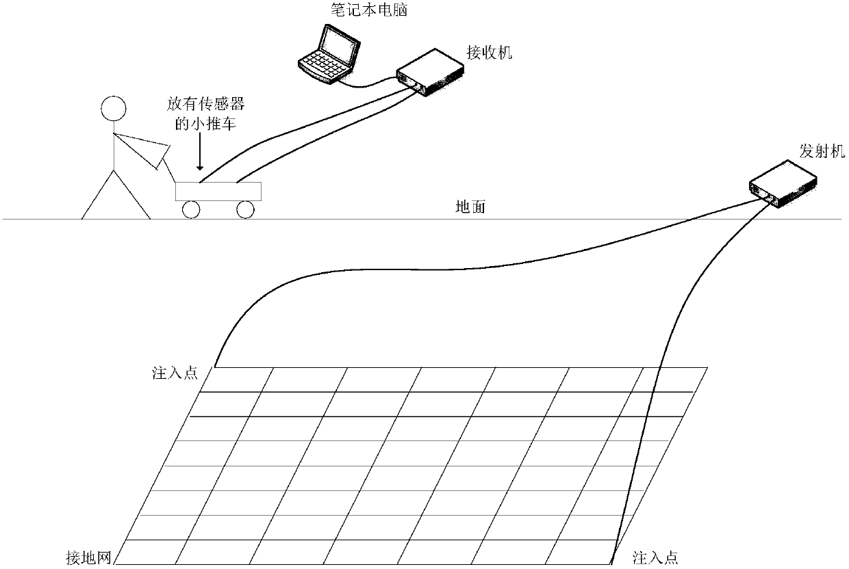
[0025] Such as figure 1 As shown, the present invention provides a substation grounding grid corrosion diagnosis system based on the induction apparent magneto-impedance method. A transmitter is connected between the two downconductor conductors of the substation grounding grid. The grid injects an excitation current with adjustable frequency to excite the surface magnetic induction intensity signal. The diagnostic system also includes a trolley placed on the ground, on which two detection coils perpendicular to each other are placed to detect magnetic induction intensity signals and transform them into induced voltage signals. In order to make the detection more convenient, encoders are installed on the wheels of the ...


PUM


Abstract

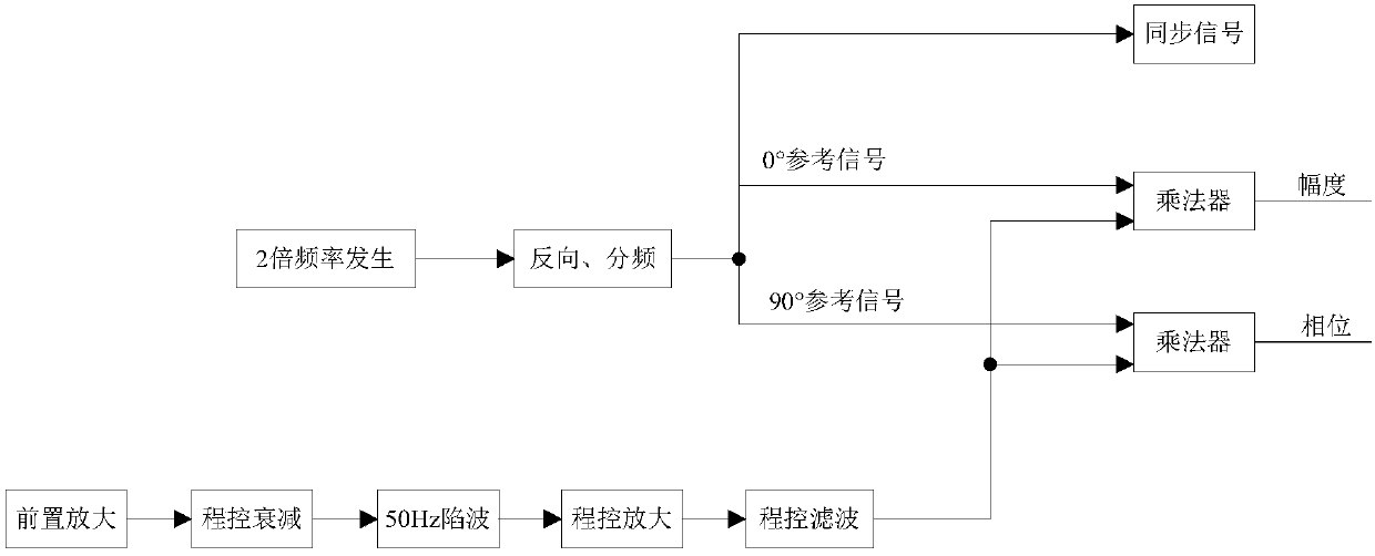
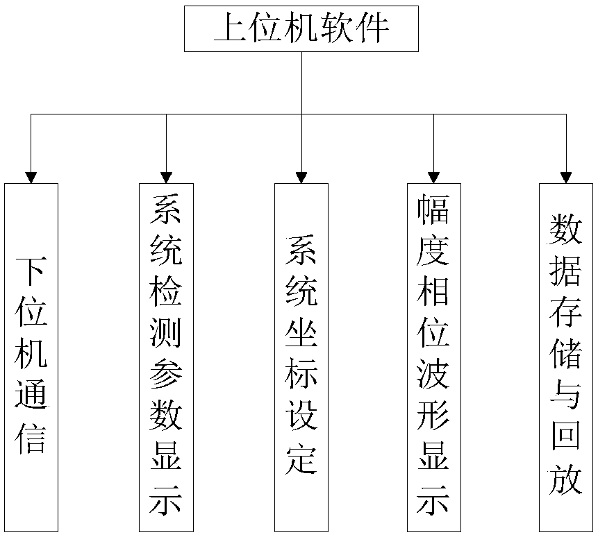
The invention discloses a system and a method for corrosion diagnosis of a grounding grid of a transformer substation on the basis of an inductive apparent magnetic impedance method. The system includes a transmitter that is connected between two down-lead conductors of the grounding grid of the transformer substation. The transmitter employs a sine excitation source and is used for injecting a frequency-adjustable excitation current into the grounding grid so as to excite a magnetic induction intensity signal of ground surface; the system also includes: a trolley arranged on the ground, on which two detection coils are arranged vertically to each other and are used for detecting the magnetic induction intensity signal and converts the magnetic induction intensity signal into an inductionvoltage signal; the detection coils are successively connected to a receiver and an upper computer, wherein the receiver is used for collecting and processing the induction voltage signal so as to acquire amplitude spectrum and phase spectrum, and the upper computer draws two-dimensional and three-dimensional figures of the amplitude and phase by means of Lab VIEW software. In the invention, by means of injection of the frequency-adjustable large excitation current and measurement of trapped wave circuits and wave filtering on hardware, the system can avoid intensive electromagnetic interference from the transformer substation and can provide more reliable measurement data.

Description


Claims


Application Information

Patent Timeline
Owner STATE GRID CORP OF CHINA
Learn More