Device for recycling waste tools of power grid structure

A technology of recycling device and power grid structure, which is applied in grain processing and other directions, can solve the problems of inability to complete crushing treatment under closed conditions and multi-stage crushing treatment.

Inactive Publication Date: 2018-03-06
刘松
View PDF10 Cites 4 Cited by
  • Summary
  • Abstract
  • Description
  • Claims
  • Application Information

AI Technical Summary

Problems solved by technology

[0006] In order to overcome the shortcomings in the prior art that the crushing process cannot be performed in multiple stages and cannot be completed in a closed condition, the technical problem to be solved by the present invention is to provide a crushing process capable of multi-stage crushing and in a closed condition Recycling device for waste tools for grid structures that have been crushed

Method used


Image

  • Device for recycling waste tools of power grid structure
  • Device for recycling waste tools of power grid structure
  • Device for recycling waste tools of power grid structure

Examples


Embodiment 1

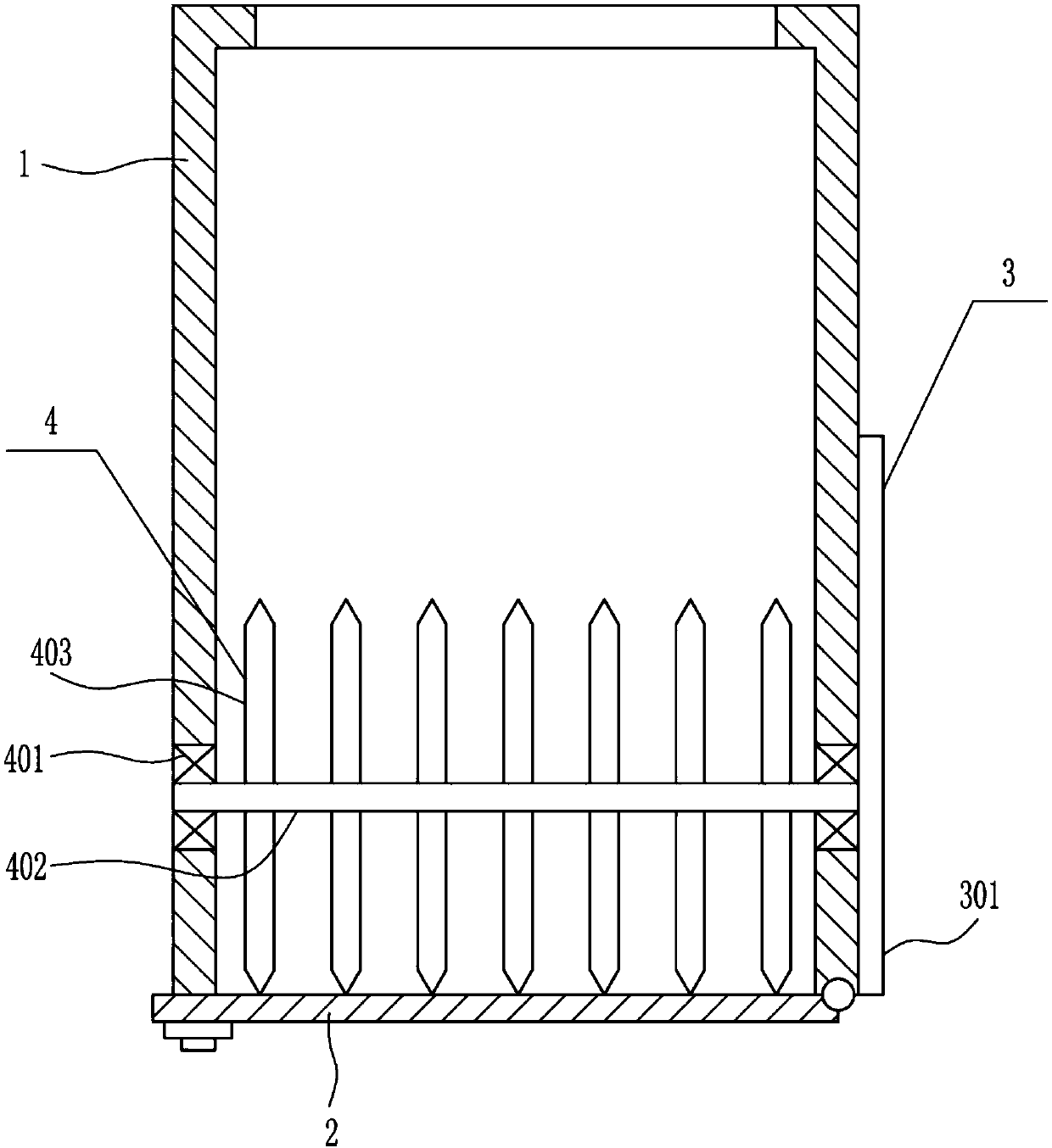
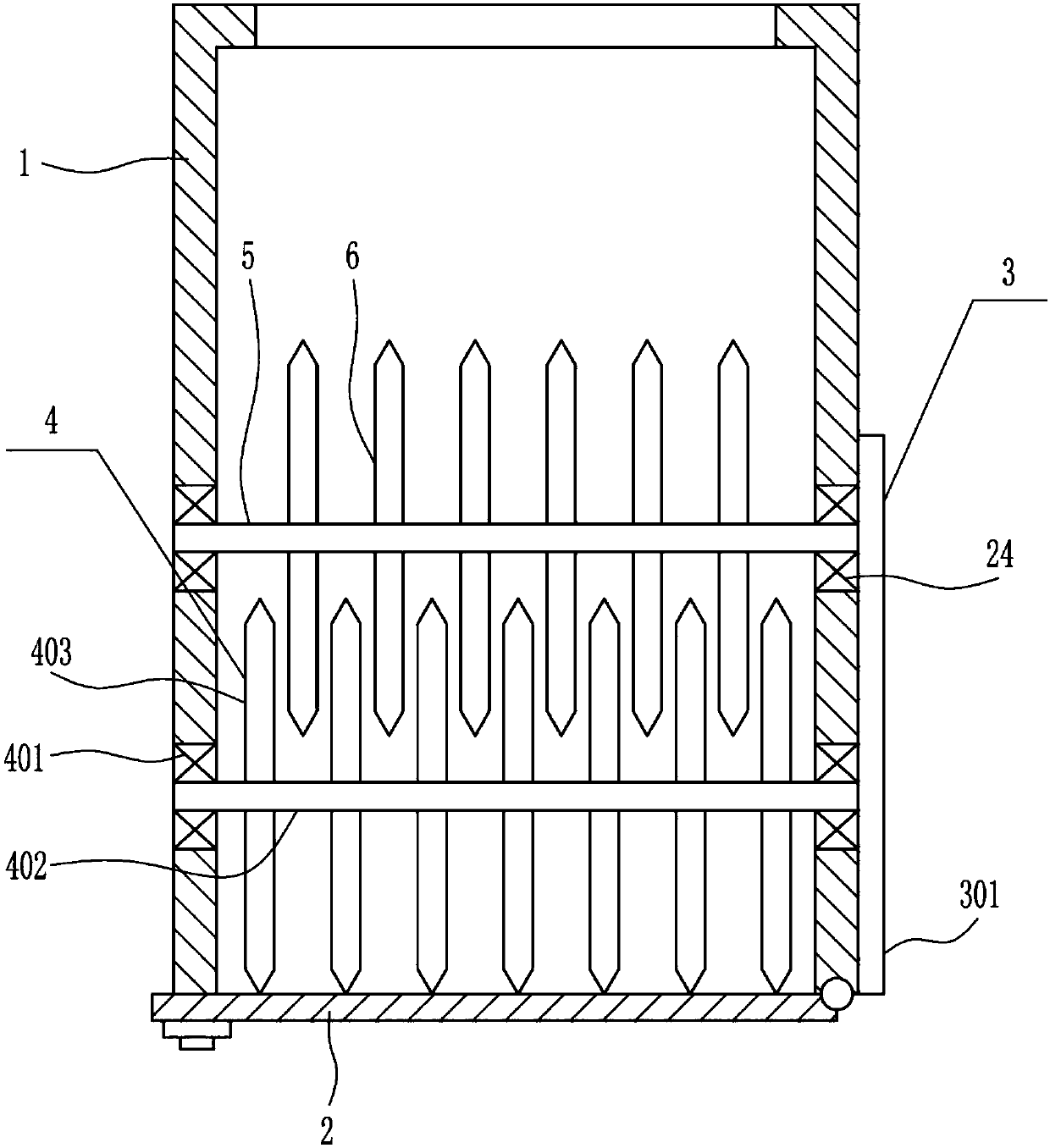
[0034] A recycling device for waste tools for power grid structure, such as Figure 1-7 As shown, it includes a box body 1, a first baffle plate 2, a driving mechanism 3 and a crushing mechanism 4, the lower part of the right side of the installation box 301 is connected with the driving mechanism 3, and the lower part of the installation box 301 is connected with the crushing mechanism 4, and the crushing mechanism 4 is connected with the crushing mechanism 4. The driving mechanism 3 is connected, and the bottom end of the right wall of the installation box 301 is rotatably connected with the first baffle plate 2, and the left part of the first baffle plate 2 is connected and fixed on the bottom end of the left wall of the installation box 301 by bolts.

Embodiment 2

[0036] A recycling device for waste tools for power grid structure, such as Figure 1-7 As shown, it includes a box body 1, a first baffle plate 2, a driving mechanism 3 and a crushing mechanism 4, the lower part of the right side of the installation box 301 is connected with the driving mechanism 3, and the lower part of the installation box 301 is connected with the crushing mechanism 4, and the crushing mechanism 4 is connected with the crushing mechanism 4. The driving mechanism 3 is connected, and the bottom end of the right wall of the installation box 301 is rotatably connected with the first baffle plate 2, and the left part of the first baffle plate 2 is connected and fixed on the bottom end of the left wall of the installation box 301 by bolts.

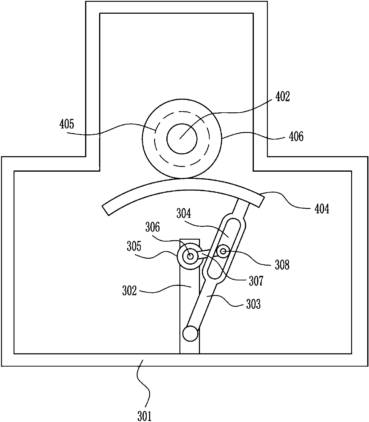
[0037] Drive mechanism 3 includes installation box 301, pole 302, swing bar 303, first motor 305, runner 306, first rotating rod 307 and slide shaft 308, and installation box 301 right side bottom is connected with installati...

Embodiment 3

[0039] A recycling device for waste tools for power grid structure, such as Figure 1-7 As shown, it includes a box body 1, a first baffle plate 2, a driving mechanism 3 and a crushing mechanism 4, the lower part of the right side of the installation box 301 is connected with the driving mechanism 3, and the lower part of the installation box 301 is connected with the crushing mechanism 4, and the crushing mechanism 4 is connected with the crushing mechanism 4. The driving mechanism 3 is connected, and the bottom end of the right wall of the installation box 301 is rotatably connected with the first baffle plate 2, and the left part of the first baffle plate 2 is connected and fixed on the bottom end of the left wall of the installation box 301 by bolts.

[0040] Drive mechanism 3 includes installation box 301, pole 302, swing bar 303, first motor 305, runner 306, first rotating rod 307 and slide shaft 308, and installation box 301 right side bottom is connected with installati...


PUM


Abstract

The invention relates to a recycling device, in particular to device for recycling waste tools of a power grid structure, and aims to solve the technical problem of providing a device which is capableof implementing multi-stage crushing treatment and crushing treatment under a sealed condition for the waste tools of the power grid structure. To solve the technical problem, the invention providesthe device for recycling the waste tools of the power grid structure. The device comprises a tank body and the like, wherein a driving mechanism is connected with the lower part of the right side of the mounting tank; a crushing mechanism is connected with the lower part inside the mounting tank; the crushing mechanism is connected with the driving mechanism; a first baffle plate is rotationally connected with the bottom end of the right wall of the mounting tank; the left part of the first baffle plate is fixed at the bottom end of the left wall of the mounting tank in a bolt connection mode.Due to adoption of the driving mechanism and the crushing mechanism, the purpose of crushing waste tools poured into the device is achieved, and by controlling an electronic push rod to stretch and withdraw, the tank body is opened and closed through a second baffle plate.

Description

technical field [0001] The invention relates to a recovery device, in particular to a recovery device for waste tools used in grid structures. Background technique [0002] Power grid structure: the layout of power plants, substations and switching stations in the power grid, and the connection mode of the voltage power lines connecting them at all levels. The relationship between the strength of the power grid and the safety and stability of the power grid operation, the quality of power supply and economic benefits. [0003] Due to the existing process of processing waste tools, waste tools need to be crushed and recycled. However, multi-stage crushing cannot be carried out during crushing, resulting in incomplete crushing. When processing, it cannot be processed under airtight conditions. The crushing process is completed, causing the debris to splash and injure the worker. [0004] Therefore, there is an urgent need to develop a recovery device for waste tools for powe...

Claims


Application Information

Patent Timeline
Patent Type & Authority Applications(China)
IPC IPC(8): B02C18/14B02C18/16B02C18/18B02C18/24B02C23/04
CPCB02C18/0084B02C18/14B02C18/16B02C18/18B02C18/24B02C2018/147B02C2018/168B02C2201/06
Inventor 刘松许迪金华夏
Owner 刘松
Why Eureka
Try Eureka