
Full-automatic bent pipe and shrunk pipe punching machine

A punching machine, fully automatic technology, applied in the direction of grinding drives, parts of grinding machine tools, machine tools suitable for grinding the edge of workpieces, etc. and other problems, to achieve the effect of complete and compact structure design

Inactive Publication Date: 2018-03-06
深圳市永顺通用机械有限公司
View PDF5 Cites 4 Cited by
  • Summary
  • Abstract
  • Description
  • Claims
  • Application Information

AI Technical Summary

Problems solved by technology

[0002] The existing punching technology for metal pipe fittings and sporting goods pipe products uses an electric motor to drive the sprocket shaft, which is transmitted to the hexagonal steel with bevel teeth, so that it can drive the feeding screw to send the material pipe to the pipe bend fixture. There are motor wire brush shafts on both sides to clean the milling pipe end burrs. After the material pipe reaches the fixture, the double-cylinder hydraulic power provides the bending deformation and tightens the material pipe. The hydraulic cylinders at both ends push the shrinking punching die to the outside and the inside to reach Closing, shrinking, punching and other actions, after the shrinking mold is completed, it will return to the outer position, and the material tube will be blocked by the stopper hook under the clamp and fall off. The existing technology cannot adjust the width of the mold according to the processing length of the tube material, nor can it be adjusted according to the length of the tube. The difference in pipe material adjusts the resilience of the elbow, and the existing technology uses a manual punch to complete it, which takes a long time, has low output, and is inefficient

Method used


Image

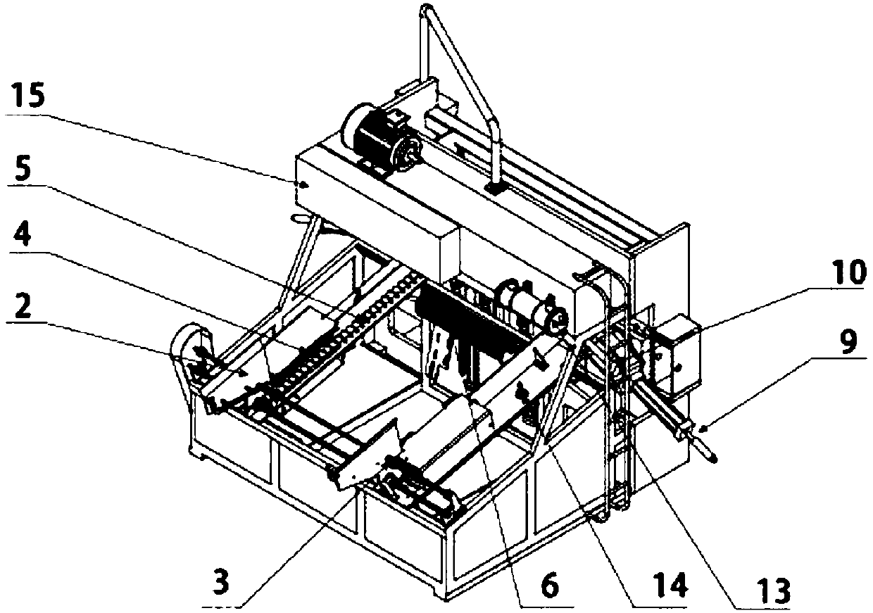
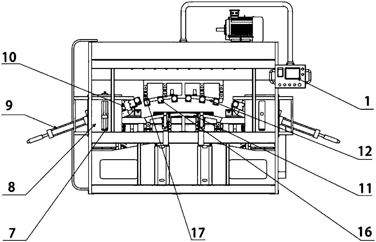
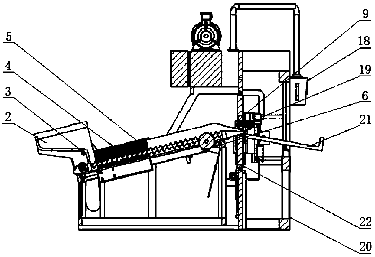
  • Full-automatic bent pipe and shrunk pipe punching machine
  • Full-automatic bent pipe and shrunk pipe punching machine
  • Full-automatic bent pipe and shrunk pipe punching machine

Examples


Embodiment Construction

[0019] The technical solutions in the embodiments of the present invention will be clearly and completely described below in conjunction with the accompanying drawings in the embodiments of the present invention. Obviously, the described embodiments are only some of the embodiments of the present invention, not all of them. Based on The embodiments of the present invention and all other embodiments obtained by persons of ordinary skill in the art without making creative efforts belong to the protection scope of the present invention.

[0020] see Figure 1-3 , the present invention provides a technical solution: a fully automatic bending and shrinking pipe punching machine, including a touch screen control electric box 1, a loading bin 2, a feeding screw 5, a pipe wiping brush 6, and an adjustable oil cylinder for shrinking molds 9 , pipe bending die 22 and punching machine main body 20, a touch screen control electric box 1 is installed on one side of the punching machine mai...


PUM


Abstract

The invention discloses a fully automatic bending and shrinking punching machine, which includes a touch screen control electric box, a loading bin, a feeding screw, a brush for wiping pipes, an adjustable oil cylinder for shrinking dies, a bending die and a main body of the punching machine. A touch screen control electric box is installed on one side of the main body of the punching machine, an electric motor is installed on the upper end of the main body of the punching machine, a bent pipe is installed on one side of the electric motor, one end of the bent pipe is connected with the touch screen control electric box, and the other end of the bent pipe is provided with a bent pipe. Pipe mold, pipe bending mold includes elbow upper clamping die and elbow lower clamping die. Both sides of the mold are equipped with shrinking mold mounting seats, and shrinking molds are installed inside the shrinking mold mounting seats. Compared with manual processes from milling tubes to bending, punching and shrinking, the entire processing process saves time and improves The production capacity reduces work injuries, and the invention has a simple structure and a reasonable design, is more humanized, and is suitable for popularization and use.

Description

technical field [0001] The invention relates to a punching machine, in particular to a fully automatic punching machine for bending and shrinking tubes. Background technique [0002] The existing punching technology for metal pipe fittings and sporting goods pipe products uses an electric motor to drive the sprocket shaft, which is transmitted to the hexagonal steel with bevel teeth, so that it can drive the feeding screw to send the material pipe to the pipe bend fixture. There are motor wire brush shafts on both sides to clean the milling pipe end burrs. After the material pipe reaches the fixture, the double-cylinder hydraulic power provides the bending deformation and tightens the material pipe. The hydraulic cylinders at both ends push the shrinking punching die to the outside and the inside to reach Closing, shrinking, punching and other actions, after the shrinking mold is completed, it will return to the outer position, and the material tube will be blocked by the st...

Claims


Application Information

Patent Timeline
IPC IPC(8): B21D35/00B21D7/06B21D7/12B21D28/28B21D41/04B21D43/05B24B9/00B24B9/04B24B47/12B24B27/033
CPCB21D35/001B21D7/06B21D7/12B21D28/28B21D35/002B21D41/04B21D43/05B24B9/007B24B9/04B24B27/033B24B47/12
Inventor 雷红通
Owner 深圳市永顺通用机械有限公司
Learn More