
Tool suspension welding positioning device

A positioning device and tooling technology, applied in auxiliary devices, manufacturing tools, welding equipment, etc., can solve problems such as customer complaints and product deflation, and achieve the effect of reducing solder joint position deviation and simple and effective protection

Inactive Publication Date: 2018-03-06
YIZHENG TONGZHOU AUTO PARTS CO LTD
View PDF0 Cites 0 Cited by
  • Summary
  • Abstract
  • Description
  • Claims
  • Application Information

AI Technical Summary

Problems solved by technology

[0003] In production, it often happens that the operator enters the torch too fast, and the welding torch hits the product due to inertia, causing the product to collapse, causing customers to complain

Method used


Image

  • Tool suspension welding positioning device

Examples


Embodiment Construction

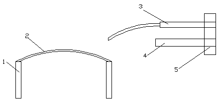
[0010] A frock suspension welding positioning device, the positioning device includes a frock 1, a welding guide device 2, a welding torch 3, and a limit steel block 4, the welding guide device 2 is arranged on the frock 1, and the device 1 has a Standardize the one-to-one corresponding marks of the solder joint positions to locate the Y-direction position of the solder joints. At the same time, the welding guide device 2 also plays a role in preventing the welding torch from hitting the part and causing the deformation of the part. The limit steel block 4 is arranged on the welding torch 3 The lower part is used to locate the position of the welding spot in the X direction. Through the effective combination of the welding guide device 2 and the limit steel block 4, the position of each welding spot at the rear sealing window of the rear bulkhead can be accurately located. At the same time, in order to avoid the phenomenon of welding conduction, a nylon block 5 is arranged betw...


PUM


Abstract

The invention relates to a tool suspension welding positioning device. The positioning device includes a tooling, a welding guide, a welding torch, and a limit steel block. The welding guide is arranged on the tool to locate the position of the welding spot in the Y direction, and the limit steel block is arranged at the lower part of the welding torch , to locate the X-direction position of the welding spot, and a nylon block is arranged between the limiting steel block and the welding torch. The welding guide device of the present invention is fixed on the tooling, and the position of the welding spot is determined by combining with the limit steel block, and combined with the nylon block to protect and position the parts more concisely and effectively, greatly reducing the position deviation of the welding point and the impact of human factors on the welding quality Impact.

Description

technical field [0001] The invention relates to a welding positioning tool, in particular to a tool hanging welding positioning device. Background technique [0002] During the hanging welding operation, due to manual operation, the position of the visual welding spot often has a deviation of 1~5mm, resulting in uneven arrangement of the spot and affecting the aesthetics, so that the quality of the welded parts cannot be guaranteed. The traditional solution is to install nylon limit blocks on the tooling to ensure that the solder joints are evenly distributed. However, due to the particularity of the parts in the visible area of ​​the back sealing window partition of the rear bulkhead welding subassembly, there is no additional installation on the tooling. The space and position of the solder joint limit. [0003] In production, it often happens that the operator enters the torch too fast, and the welding torch hits the product due to inertia, causing the product to collaps...

Claims


Application Information

Patent Timeline
Patent Type & Authority Applications(China)
IPC IPC(8): B23K37/02
CPCB23K37/0241
Inventor 陆志良
Owner YIZHENG TONGZHOU AUTO PARTS CO LTD
Learn More