
Lubricating structure for motorcycle clutch

A lubricating structure and clutch technology, which is applied in the field of clutches, can solve problems such as environmental pollution, clutch lubrication, and inconvenient use of clutches, and achieve the effects of facilitating secondary use, ensuring comprehensiveness, and ensuring real-time lubrication

Inactive Publication Date: 2018-03-06
WUXI CHUANGGE TECH CO LTD
View PDF0 Cites 1 Cited by
  • Summary
  • Abstract
  • Description
  • Claims
  • Application Information

AI Technical Summary

Problems solved by technology

When the clutch is used, it needs to be lubricated. Most of the existing lubricating devices simply add lubricating oil to the inside, which is easy to cause waste of lubricating oil, and it is difficult to fully lubricate the inside of the clutch. When there is too much lubricating oil It will pollute the surrounding environment and bring inconvenience to the use of the clutch. For this reason, we propose a lubrication structure for motorcycle clutches

Method used


Image

  • Lubricating structure for motorcycle clutch
  • Lubricating structure for motorcycle clutch
  • Lubricating structure for motorcycle clutch

Examples


Embodiment Construction

[0019] In order to make the technical means, creative features, goals and effects achieved by the present invention easy to understand, the present invention will be further described below in conjunction with specific embodiments.

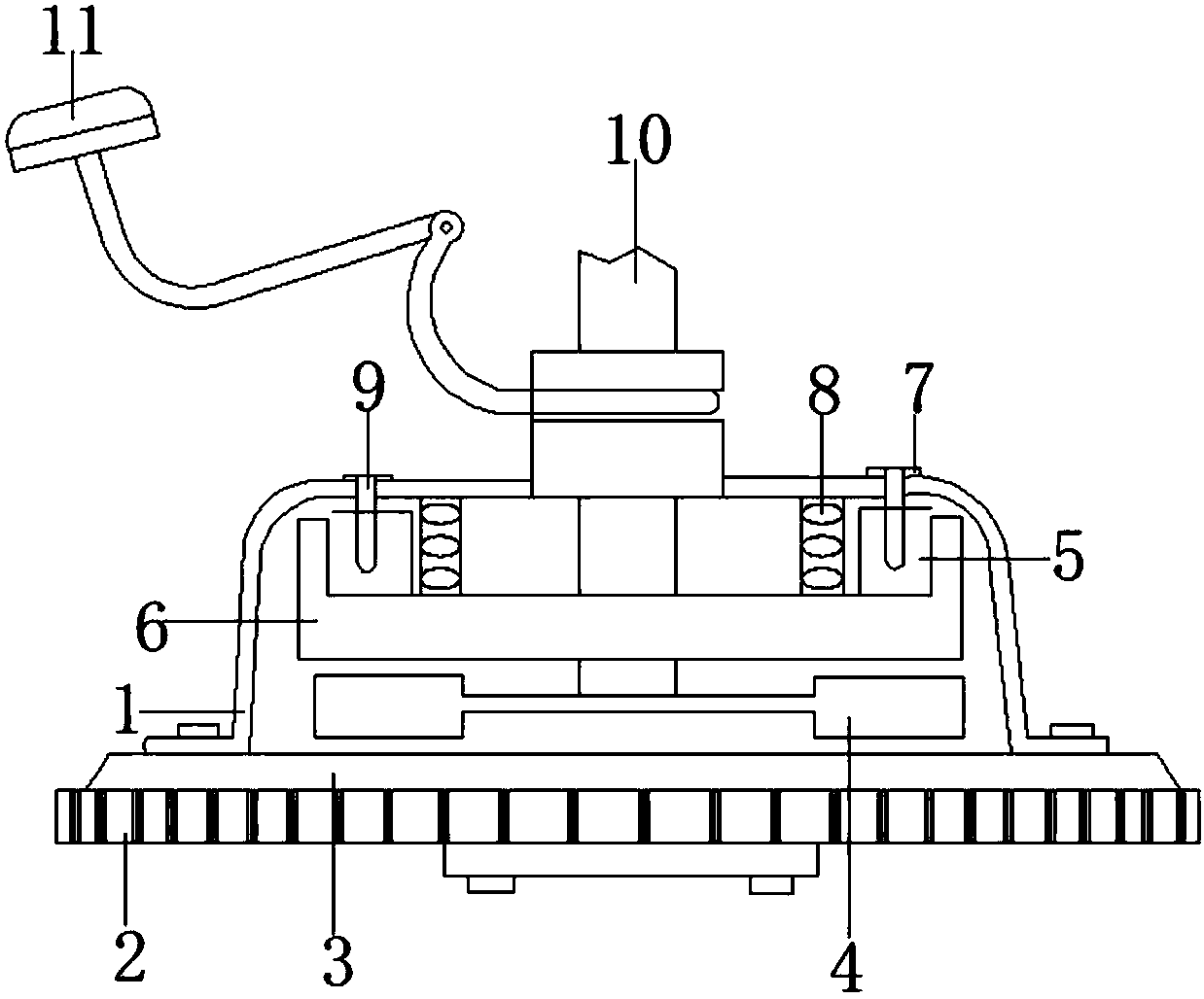
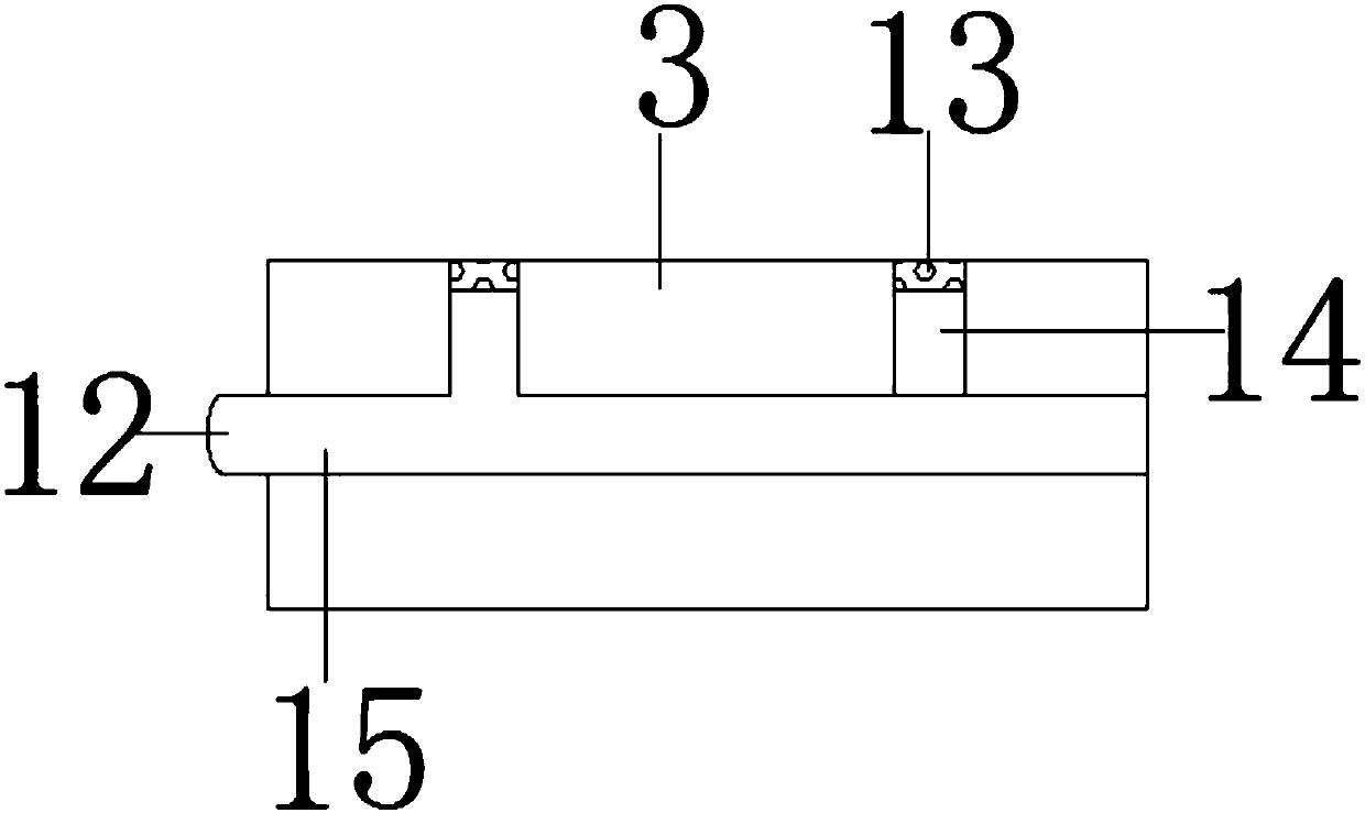
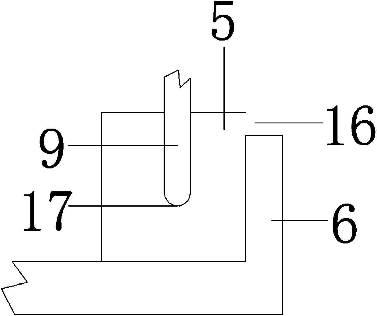
[0020] Such as Figure 1-3 As shown, a lubricating structure for a motorcycle clutch includes an outer cover 1, a gearbox input shaft 10 and a clutch pedal 11, a gearbox input shaft 10 is arranged in the middle of the outer cover 1, and a clutch pedal is arranged on the outer side of the outer cover 1 11 and the clutch pedal 11 is sleeved on one end of the gearbox input shaft 10, the inside of the cover 1 is provided with a pressure plate 6 and the pressure plate 6 is connected to the top of the cover 1 through a spring 8, and the two sides of the upper part of the pressure plate 6 are provided with a fuel tank 5 and a fuel tank 5 A pressure rod 9 is arranged inside, the top of the pressure rod 9 is connected to the threaded cap 7 and the threaded...


PUM


Abstract

The invention discloses a lubricating structure for a motorcycle clutch, which comprises an outer cover, a gearbox input shaft and a clutch pedal. A gearbox input shaft is arranged in the middle of the outer cover, and a clutch pedal is arranged on the outer side of the outer cover, and the clutch pedal is socketed. At one end of the input shaft of the gearbox, a pressure plate is provided inside the outer cover, and the pressure plate is connected to the top of the outer cover through a spring. An oil tank is arranged on both sides of the upper part of the pressure plate, and a pressure rod is arranged inside the oil tank. The top of the pressure rod is connected to a threaded cap and threaded The cap is located on the surface of the outer cover, and the bottom of the pressure rod is provided with a drip port. The present invention can increase the lubricating oil inside the clutch, which is convenient for replenishing the lubricating oil inside the clutch in time, and can fully lubricate the inside of the clutch, ensuring the comprehensiveness of the clutch lubrication, and can pass the excess lubricating oil through the clutch after lubricating the clutch. The filter screen is collected in the central tube, which is convenient for the secondary use of the lubricating oil, and can also overflow the lubricating oil, causing inconvenience to use.

Description

technical field [0001] The invention relates to the technical field of clutches, in particular to a lubricating structure for a motorcycle clutch. Background technique [0002] The clutch is located in the flywheel housing between the engine and the gearbox. The clutch assembly is fixed on the rear plane of the flywheel with screws. It is a device that transmits the engine power of a car or other power machinery to the axle in the form of a switch. During the driving process of the car, the driver can step on or release the clutch pedal as needed to temporarily separate and gradually engage the engine and the transmission, so as to cut off or transmit the power input from the engine to the transmission. When the clutch is used, it needs to be lubricated. Most of the existing lubricating devices simply add lubricating oil to the inside, which is easy to cause waste of lubricating oil, and it is difficult to fully lubricate the inside of the clutch. When there is too much lubr...

Claims


Application Information

Patent Timeline
IPC IPC(8): F16D13/74
CPCF16D13/74
Inventor 孙爱珍
Owner WUXI CHUANGGE TECH CO LTD
Learn More