Connection element for hydraulic pipe

The technology of a connector and hydraulic tube, which is used in the direction of pipe/pipe joint/pipe parts, seal connections, through components, etc., which can solve problems such as the rupture of the hydraulic tube connector card cover, damage to the oil pipe, and cannot achieve, to avoid excessive movement suffering. damage, ensure working stability, and improve airtight performance

Inactive Publication Date: 2018-03-06
黄磊
View PDF0 Cites 4 Cited by
  • Summary
  • Abstract
  • Description
  • Claims
  • Application Information

AI Technical Summary

Problems solved by technology

[0002] The traditional hydraulic pipe joint ferrule has only one sealing edge in structure, which belongs to the metal contact seal. Its function is to tighten the nut when the oil pipe and the pipe joint are assembled and connected, and squeeze the tapered surface of the taper hole of the hydraulic pipe joint body. The cutting edge of the hydraulic pipe joint ferrule cuts into the surface of the oil pipe to achieve a metal contact seal. If the nut is tightened excessively, it will cause the cutting edge of the hydraulic pipe joint ferrule to cut into the oil pipe excessively, resulting in the rupture of the hydraulic pipe joint ferrule; and the traditional The working pressure that the ferrule of the hydraulic pipe joint can bear does not exceed 40Mpa, and the rupture of the ferrule of the hydraulic pipe joint may occur after exceeding
[0003] Traditional hydraulic pipe joint ferrules are easily deformed, cracked and leaked when the impact force and vibration intensity are high, the temperature is above 100°C, the vibration frequency is above 40Hz, the pressure is above 60Mpa, and the acidic and mine working environment , the service life is short, and it cannot meet the working requirements of high-end hydraulic pipe joints in harsh environments where the pressure is above 60Mpa, acid, mine, temperature is above 100°C, and vibration frequency is above 40Hz.

Method used


Image

  • Connection element for hydraulic pipe

Examples


Embodiment 1

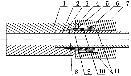
[0021] Such as figure 1 As shown, this embodiment includes a joint body 1, a hydraulic oil pipe 2 and a nut 7 threadedly fitted with the hydraulic oil pipe 2. The joint body 1 is sleeved on the hydraulic oil pipe 2, and at the connecting end of the joint body 1 and the hydraulic oil pipe 2 An inner tapered interface 3 is provided, and an active groove 10 is opened at the end of the nut 7 facing the joint body 1, and the ferrule is installed in the active groove 10 and its inner wall is bonded to the outer peripheral wall of the hydraulic oil pipe 2. The ferrule is composed of a buffer part 6 and a sealing part 4. The buffer part 6 is an elastic metal ring. The outer peripheral wall of the buffer part 6 is provided with an expansion part protruding outward along its radial direction and having an arc-shaped cross-section. The expansion part The arc top of the arc is in contact with the upper wall of the movable groove 10, the sealing part 4 is connected with the side wall of th...


PUM


Abstract

The invention discloses a hydraulic pipe connector, which includes a joint body, a hydraulic oil pipe and a nut. There is a movable groove at one end of the joint body, the ferrule is installed in the movable groove and its inner wall is attached to the outer peripheral wall of the hydraulic oil pipe, the ferrule is composed of a buffer part and a sealing part, and the sealing part is along the axial direction of the ferrule toward The inner conical surface extends inside the interface, and there is an annulus between the first sealing surface, the second sealing surface and the hydraulic oil pipe. The first sealing surface is in close contact with the outer peripheral wall of the hydraulic oil pipe, the annular space is maintained between the second sealing surface and the outer peripheral wall of the hydraulic oil pipe, the inner wall of the sealing part body is in close contact with the outer peripheral wall of the hydraulic oil pipe, and the side of the buffer The wall and the arc-shaped expansion part on the outer wall are respectively closely attached to the side walls of the movable groove, so as to ensure the airtightness of the ferrule assembly under high temperature and high pressure conditions.

Description

technical field [0001] The invention relates to a hydraulic pipe, in particular to a hydraulic pipe connector. Background technique [0002] The traditional hydraulic pipe joint ferrule has only one sealing edge in structure, which belongs to the metal contact seal. Its function is to tighten the nut when the oil pipe and the pipe joint are assembled and connected, and squeeze the tapered surface of the taper hole of the hydraulic pipe joint body. The cutting edge of the hydraulic pipe joint ferrule cuts into the surface of the oil pipe to achieve a metal contact seal. If the nut is tightened excessively, it will cause the cutting edge of the hydraulic pipe joint ferrule to cut into the oil pipe excessively, resulting in the rupture of the hydraulic pipe joint ferrule; and the traditional The working pressure that the ferrule of the hydraulic pipe joint can bear does not exceed 40Mpa, and the rupture accident of the ferrule of the hydraulic pipe joint may occur after exceedi...

Claims


Application Information

Patent Timeline
Patent Type & Authority Applications(China)
IPC IPC(8): F16L19/05
CPCF16L19/043F16L19/05
Inventor 黄磊
Owner 黄磊
Why Eureka
Try Eureka