Optical system for LED stage lamp

An optical system and LED light source technology, which is applied in the field of optical systems, can solve problems such as the difficulty of taking into account the uniformity of the spot and the light effect at the same time, and achieve the effect of improving the uniformity of the spot, high light efficiency, and improving the uniformity

Pending Publication Date: 2018-03-06
GUANGZHOU DASEN LIGHTING ELECTRONICS
View PDF8 Cites 8 Cited by
  • Summary
  • Abstract
  • Description
  • Claims
  • Application Information

AI Technical Summary

Problems solved by technology

[0003] The technical problem to be solved by the present invention is: it is difficult to balance

Method used


Image

  • Optical system for LED stage lamp
  • Optical system for LED stage lamp
  • Optical system for LED stage lamp

Examples


Embodiment 1

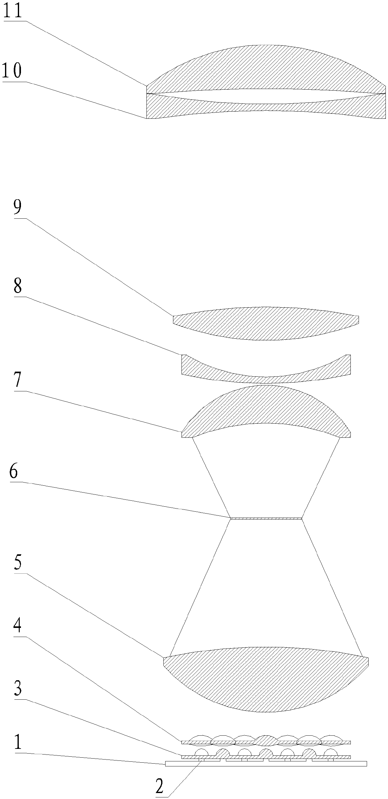
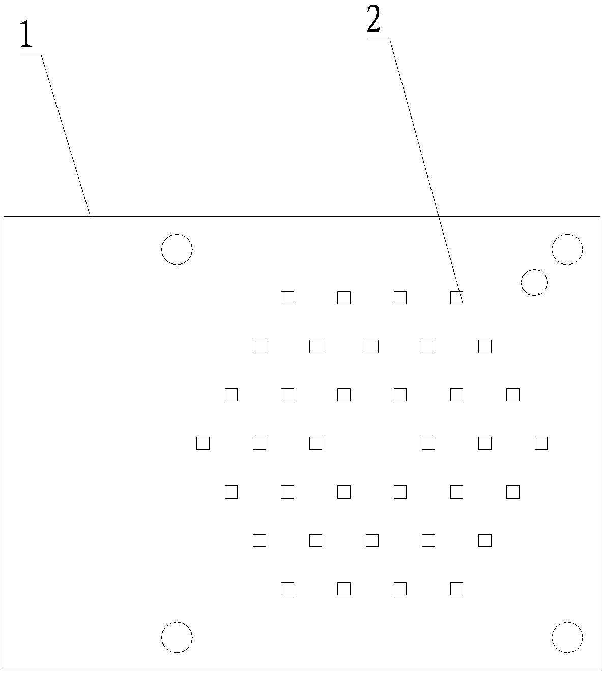
[0030] refer to figure 1 and figure 2 , the number of the LED lamp beads 2 is not less than 18, and no lamp beads are placed in the center of the substrate 1 . In this embodiment, no LED lamp bead 2 is placed at the center of the substrate 1, so that the uniformity of the light spot can be controlled. The greater the number of lamp beads, the more beneficial it is for light mixing. The uneven distribution of light intensity of a single LED light source can be achieved by interfering and superimposing light waves of more light sources and complementing each other to enhance the effect of light mixing and uniform light. Setting the number of 18 is the minimum number required for two hexagonal arrays. If the number is less than 18, it is difficult to increase the power of the optical system, and the second is that the uniformity of the spot will be reduced.

Embodiment 2

[0032] refer to figure 1 and figure 2 The radius of curvature of the light-incident surface of the first lens 12 is 4.5-10.0 mm, the radius of curvature of the light-exit surface is 2-6 mm, and the distance between the first lens 12 and the LED lamp bead 2 is 0.05-0.30 mm. In this embodiment, the distance between the first lens 12 and the LED lamp bead 2 is installed too low, which is not conducive to the installation operation, and the distance is too high, which is not conducive to light collection and affects the light collection efficiency. Therefore, an appropriate distance can be selected within the range of 0.05-0.30 mm according to actual needs. The first lens 12 and the second lens 13 together form a condenser lens group with an effective focal length EFFL value of 3.5mm. The range of curvature radii of the two single lenses depends on the size of the effective focal length. The reason why the effective focal length of the condenser lens group of this program is set...

Embodiment 3

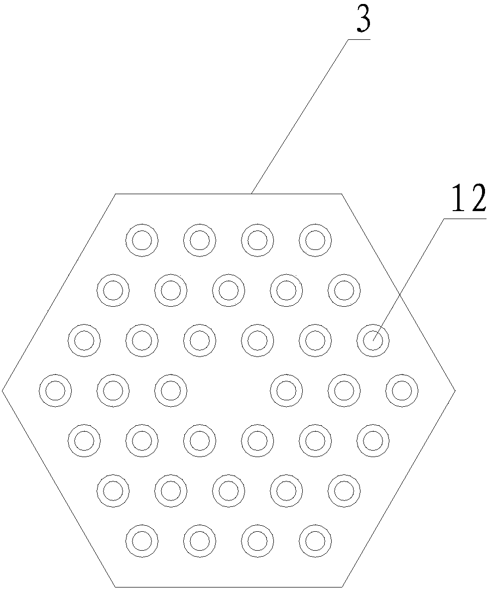
[0034] refer to figure 1 and image 3, the first condenser lens group 3 includes a plurality of first lenses 12; the first lenses 12 are arranged in one-to-one correspondence with the LED lamp beads 2. In this embodiment, the number of first lenses 12 is determined by the number of LED lamp beads 2, and each LED lamp bead 2 is provided with a corresponding first lens 12. After focusing, improve the uniformity of single beam.


PUM

PropertyMeasurementUnit
Diameteraaaaaaaaaa

Abstract

The invention discloses an optical system for an LED stage lamp. The optical system for the LED stage lamp comprises an LED light source assembly, a light condensing lens assembly and an imaging lensassembly which are sequentially arranged; the LED light source assembly comprises a base plate and LED lamp beads; the LED lamp beads are arranged on the plane of the base plate in a regular hexagon array, so that light ray emitted out of a power source can be more uniform, the light ray loss is reduced, and the light collecting efficiency is improved; and light beams emitted out of the LED lightsource assembly can be condensed into collimated uniform light beams by the light condensing lens assembly, the uniformity degree of the single light beam is improved, and meanwhile the light spot uniformity degree is improved; and after the aggregated uniform light beam penetrates a light composition lens, the multiple collimated light beams are focused onto the focus point position of light composition lens, the light ray is projected after passing through the imaging lens assembly, and a clear pattern high in light efficacy and high in light spot quality is obtained.

Description

technical field [0001] The invention relates to an optical system for stage lamps, in particular to an optical system for LED stage lamps. Background technique [0002] At present, the light sources used in stage pattern lamps have gradually replaced metal halide discharge bulb light sources with LED light sources. In order to improve the light efficiency of LED light sources and the uniformity of projected light spots, companies and engineers in the industry have successively adopted multiple LEDs and condenser lenses. Arrangement and combination , plus a series of components such as a fly-eye lens for light uniformity and a light-combining lens for re-condensation to form a high-power light source module. Although the LED light source module using this technology has a spot uniformity of ≥90% after projection, the light output efficiency It is only between 70-80%, which is not ideal (luminous efficiency of LED module = output luminous flux after passing through the light s...

Claims


Application Information

Patent Timeline
IPC IPC(8): F21K9/20F21V5/04F21V19/00F21Y115/10
CPCF21K9/20F21V5/04F21V19/001F21Y2115/10
Inventor 许法卿薛金山
Owner GUANGZHOU DASEN LIGHTING ELECTRONICS
Why Eureka
Try Eureka