
Light emitting diode

A light-emitting device and light-emitting element technology, which is applied in the direction of electrical components, electric solid-state devices, circuits, etc., can solve the problems of unsatisfactory brightness and difficulty in providing full-circle light color rendering, so as to improve performance and reliability, improve color rendering, Improve the falloff effect

Inactive Publication Date: 2018-03-06
EVERLIGHT ELECTRONICS
View PDF3 Cites 0 Cited by
  • Summary
  • Abstract
  • Description
  • Claims
  • Application Information

AI Technical Summary

Problems solved by technology

[0006] An object of the present invention is to provide a light emitting device to solve the problems that the existing light emitting devices are difficult to provide all-round light and / or the color rendering or brightness are not ideal

Method used


Image

  • Light emitting diode
  • Light emitting diode
  • Light emitting diode

Examples


Embodiment Construction

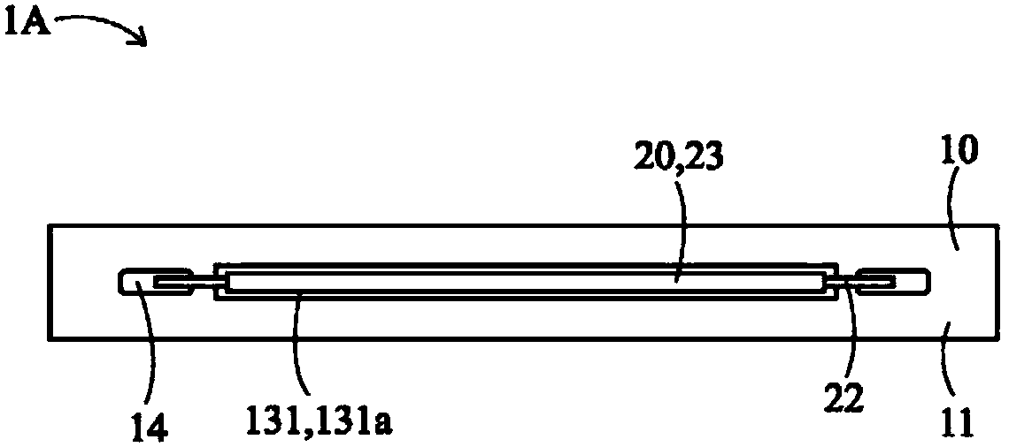
[0056] see Figure 2A to Figure 3A As shown, it is the top view, bottom view and front view of the light emitting device according to the first preferred embodiment of the present invention. The light emitting device 1A includes a substrate 10 and at least one LED light emitting element 20 , and the technical content of each element is described as follows.

[0057] The substrate 10 can be a printed circuit board (PCB), which includes a first surface 11 , a second surface 12 , at least one light-transmitting region 13 and at least two metal pads 14 . The first surface 11 and the second surface 12 are arranged opposite to each other, and both are the light-emitting surfaces of the light-emitting device 1A, which means that light can be emitted from the first surface 11 and the second surface 12 in two opposite directions away from the substrate 10 (ie, the normal direction). , so that the light-emitting device 1A can provide a full-circle light effect.

[0058] At least one l...


PUM

PropertyMeasurementUnit
Particle sizeaaaaaaaaaa

Abstract

The invention provides a light emitting diode. The light emitting diode includes a substrate and at least one LED light emitting element. The substrate includes a first surface, a second surface, at least one light penetrating region and at least two metal linings. The light penetration region is configured to extend from the first surface to the second surface. The two metal linings are disposedon the first surface. The light penetrating region is disposed between the two metal linings. The LED light emitting element is disposed inside the light penetrating region, and is in electrical connection to the two metal linings. Therefore, the light emitting apparatus can provide omnidirectional light-emitting effects. The invention also provides a fluorescent body which can be applied to the aforementioned LED light emitting elements and the like light emitting elements so as to make the light emitting element to have excellent color rendering, brightness and / or reliability.

Description

technical field [0001] The present invention relates to a light emitting device, in particular to a light emitting device capable of providing a full-circle light emitting effect. Background technique [0002] Since the manufacturing cost of light-emitting diodes (LEDs) is reduced, and LEDs have the characteristics of high brightness and long service life, LEDs are widely used in various light-emitting devices, light-emitting elements or lighting devices, such as lamp tubes. Taking the existing LED application as a lamp tube as an example, a plurality of LED chips 91 are arranged on a surface 921 of a substrate 92, and emit light toward a direction away from the surface 921 (such as Figure 1A and Figure 1B shown). [0003] However, under this setting, the light emitted by the LED chip 91 will be shielded by the substrate 92, so that the light output direction of the overall device is mainly in a direction away from the surface 921 of the substrate 92, and there is only a ...

Claims


Application Information

Patent Timeline
IPC IPC(8): H01L25/075H01L33/48H01L33/50H01L33/58H01L33/62
CPCH01L25/0753H01L33/48H01L33/504H01L33/58H01L33/62
Inventor 林晏申赖俊铭吕侊懋陈啟鸣苏鸿彦蔡名杰
Owner EVERLIGHT ELECTRONICS
Learn More