Cone-shaped motor

A conical motor and front cover technology, applied in the direction of electrical components, electromechanical devices, electric components, etc., can solve the problems of stator and rotor collision, low installation efficiency, and motor scrapping, so as to reduce the defective rate, improve installation efficiency, The effect of transmission stability

Inactive Publication Date: 2018-03-06
田曼丽
View PDF0 Cites 4 Cited by
  • Summary
  • Abstract
  • Description
  • Claims
  • Application Information

AI Technical Summary

Problems solved by technology

[0002] In the existing production technology of conical motors, the rotor is inserted into the stator during installation, and the conical stator and the conical rotor of the conical motor have a slight deflection of the rotor during the installation process, which is likely to cause collision between the stator and the rotor. The motor is scrapped. Due to the complex structure, low installation efficiency and inconvenient maintenance of the existing conical motor, it is urgent to improve the structure of the conical motor

Method used


Image

  • Cone-shaped motor

Examples


Embodiment 1

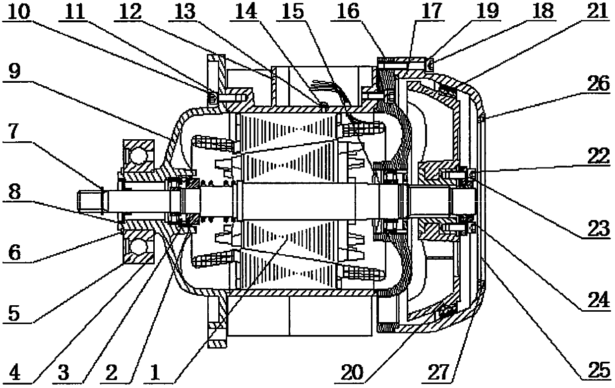
[0016] Such as figure 1 As shown, a conical motor includes a rotor assembly 1 and a stator assembly 12, the rotor assembly 1 passes through the inside of the stator assembly 12, and the left end surface of the stator assembly 12 is connected with a front Cover 9, the right end surface of the stator assembly 12 is connected with a rear cover 16, the top of the stator assembly 12 is provided with a screw B13, the installation place of the screw B13 is provided with a ground plate 14, and the front The connection between the cover 9 and the stator assembly 12 is provided with a screw A10 and a washer A11. The outer contour of the front cover 9 is bowl-shaped, and the center of the front cover 9 is a through circular thin tube. The center of the front cover 9 passes through the rotor assembly 1, the outer wall of the thin tube at the left end of the front cover 9 is provided with a single row radial ball bearing 5, and the left end surface of the thin tube at the left end of the f...

Embodiment 2

[0019] Such as figure 1 As shown, a conical motor includes a rotor assembly 1 and a stator assembly 12, the rotor assembly 1 passes through the inside of the stator assembly 12, and the left end surface of the stator assembly 12 is connected with a front Cover 9, the right end surface of the stator assembly 12 is connected with a rear cover 16, the top of the stator assembly 12 is provided with a screw B13, the installation place of the screw B13 is provided with a ground plate 14, and the front The connection between the cover 9 and the stator assembly 12 is provided with a screw A10 and a washer A11. The outer contour of the front cover 9 is bowl-shaped, and the center of the front cover 9 is a through circular thin tube. The center of the front cover 9 passes through the rotor assembly 1, the outer wall of the thin tube at the left end of the front cover 9 is provided with a single row radial ball bearing 5, and the left end surface of the thin tube at the left end of the f...


PUM


Abstract

The invention relates to a conical motor, which includes a rotor assembly and a stator assembly. The two ends of the stator assembly are provided with a front cover and a rear cover. The right end of the rear cover is provided with an end cover, and the center of the end cover is provided with a window. On the rotor shaft of the rotor assembly, there are retaining ring B, front cover, retaining cover B, one-way thrust ball bearing, retaining ring A, spacer, spring, retaining ring D, rear cover, fan brake wheel and lock The nut is tightened, and the output shaft section of the motor is provided with a single-row radial ball bearing, which facilitates the installation and use of the conical motor; the invention has the advantages of reasonable structure, stable performance, fast braking, dustproof, safe and reliable.

Description

technical field [0001] The invention belongs to the field of motors, in particular to a conical motor. Background technique [0002] In the existing production technology of conical motors, the rotor is inserted into the stator during installation, and the conical stator and the conical rotor of the conical motor have a slight deflection of the rotor during the installation process, which is likely to cause collision between the stator and the rotor. The motor is scrapped, because the existing conical motor has complex structure, low installation efficiency and inconvenient maintenance, so it is urgent to improve the structure of the conical motor. Contents of the invention [0003] The purpose of the present invention is to overcome the deficiencies of the prior art, and provide a compact, low-cost, durable conical motor. [0004] The object of the present invention is achieved as follows: a conical motor, which includes a rotor assembly and a stator assembly, the rotor ...

Claims


Application Information

Patent Timeline
Patent Type & Authority Applications(China)
IPC IPC(8): H02K5/173H02K5/04H02K7/10
CPCH02K5/173H02K5/04H02K7/10
Inventor 田曼丽
Owner 田曼丽
Why Eureka
Try Eureka