Network load balancing method, equipment and system

A network device and network load technology, applied in the field of network communication, can solve problems such as ineffective use of paths and uneven load sharing, and achieve the effects of improving network utilization, avoiding state and path information, and optimizing effects

Active Publication Date: 2018-03-06
HUAWEI TECH CO LTD
View PDF6 Cites 6 Cited by
  • Summary
  • Abstract
  • Description
  • Claims
  • Application Information

AI Technical Summary

Problems solved by technology

However, flow-based load balancing has the problem of uneven load sharing, and some paths in the network may not be effectively utilized

Method used


Image

  • Network load balancing method, equipment and system
  • Network load balancing method, equipment and system
  • Network load balancing method, equipment and system

Examples


Embodiment 1

[0060] Such as image 3 As shown, Example 1 of the present invention provides a method 300 for network load balancing, including:

[0061] Step 310, the terminal device provides P logical channels, where P is the maximum number of load balancing paths P in the network, and P is an integer greater than or equal to 2;

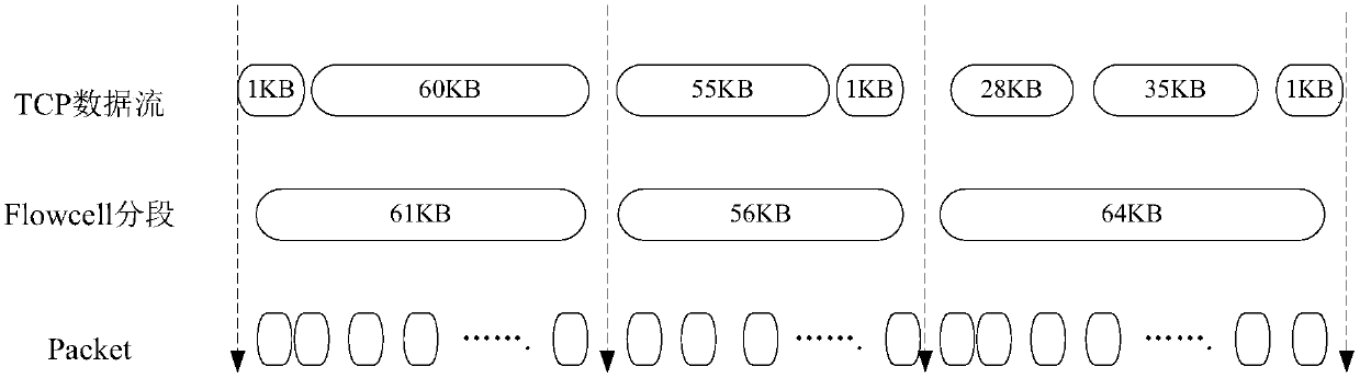
[0062] Step 320, the terminal device divides the data stream to be sent in units of stream segments to generate multiple sub-data streams;

[0063] Step 330, the terminal device maps the multiple sub-data streams to the P logical channels, and sends them to the network device.

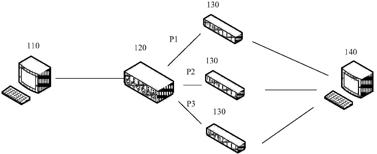
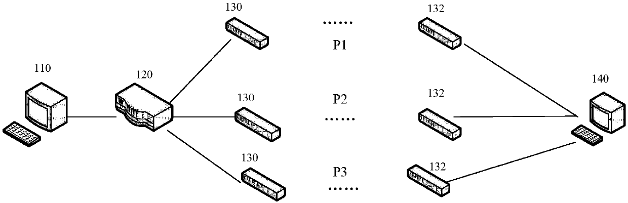
[0064] Specifically, the maximum network load balancing path number P refers to the maximum number of paths from a certain node to another node in the entire network.

[0065] There are multiple implementation methods for the terminal device to obtain the maximum load balancing path number P value of the network:

[0066] For example, the first implementation method is: set the maximum...

Embodiment 2

[0088] Such as Figure 5 As shown, Embodiment 2 of the present invention provides a method 500 for network load balancing, including:

[0089] Step 510, the network device receives multiple sub-data streams from the upstream node, where each sub-data stream carries a flow segment identifier;

[0090] Step 520: Perform a hash operation on the remainder of P according to the quintuple of the sub-data flow and the flow segment identifier, and map it to multiple physical links and send it to the next hop node, where P is the maximum load of the network The number of balanced paths, P is an integer greater than or equal to 2.

[0091] The next-hop node may be an intermediate node (network device), or a destination node, which is a terminal device to which the multiple sub-data streams finally arrive.

[0092] Specifically, a network device identifies a message belonging to a logical channel through six-tuple information. The so-called six-tuple includes the traditional five-tuple...

Embodiment 3

[0099] Such as Figure 8 As shown, another embodiment of the present invention provides a terminal device 800, the terminal device 800 includes a processor 810 and a transceiver 820, wherein:

[0100] The processor 810 is configured to provide P logical channels, where P is the maximum number of load balancing paths in the network, and P is an integer greater than or equal to 2; the data stream to be sent is divided into flow segments to generate multiple sub-data flow;

[0101] The transceiver 820 is configured to map the multiple sub-data streams to the P logical channels and send them to the network device.

[0102] Wherein, each sub-data flow carries a flow segmentation identifier.

[0103] Specifically, there are multiple ways to obtain the maximum number of load balancing paths P in the network:

[0104] For example, the first implementation method is: set the maximum number of load balancing paths P in the network as a part of the network protocol, and the terminal d...


PUM


Abstract

The embodiment of the invention provides a network load balancing method, including the following steps: terminal equipment provides P logical channels, wherein P represents the network maximum load balancing path number, and P is an integer greater than or equal to 2; the terminal equipment partitions a data stream to be sent in a unit of stream segments to form multiple sub-data streams; and theterminal equipment maps the multiple sub-data streams to the P logical channels and sends the sub-data streams to network equipment. According to the scheme of the invention, the data stream to be sent is partitioned in the unit of stream segments and mapped to the multiple logical channels, a fine-grained and more-balanced load sharing technical scheme can be implemented in the network, the network utilization can be effectively improved, and the load balancing effect can be optimized; and meanwhile, the phenomenon that the network equipment records the state and path information of a singledata stream can be avoided.

Description

technical field [0001] The present invention relates to the technical field of network communication, in particular to a network load balancing method, device and system. Background technique [0002] In a data communication network, there are usually multiple different links that can reach the same destination address. If the traditional routing technology is used, the message sent to the destination address can only use one of the links, which cannot effectively use network resources. Using load balancing technology, the traffic is distributed to multiple links according to certain rules, which can improve link utilization, and can also back up the data transmission of failed links. In the current prior art, a relatively common load balancing technology is an equal-cost multi-path (Equal Cost Multi-Path, ECMP) technology to achieve the purpose of multi-path load balancing and link backup. [0003] With the load balancing technology, packets destined for the same destinat...

Claims


Application Information

Patent Timeline
Patent Type & Authority Applications(China)
IPC IPC(8): H04L12/803H04L12/851
CPCH04L47/125H04L47/2441H04L47/2483
Inventor 龚志波高静
Owner HUAWEI TECH CO LTD
Why Eureka
Try Eureka