
Rolling-element bearing unit

A technology of rolling bearings and rolling elements, applied in rolling contact bearings, roller bearings, bearing components, etc., can solve problems such as shaft corrosion, and achieve the effect of simplified installation

Active Publication Date: 2018-03-06
SCHAEFFLER TECH AG & CO KG
View PDF10 Cites 1 Cited by
  • Summary
  • Abstract
  • Description
  • Claims
  • Application Information

AI Technical Summary

Problems solved by technology

Fluid that accumulates there can cause corrosion to the shaft

Method used


Image

  • Rolling-element bearing unit
  • Rolling-element bearing unit
  • Rolling-element bearing unit

Examples


Embodiment Construction

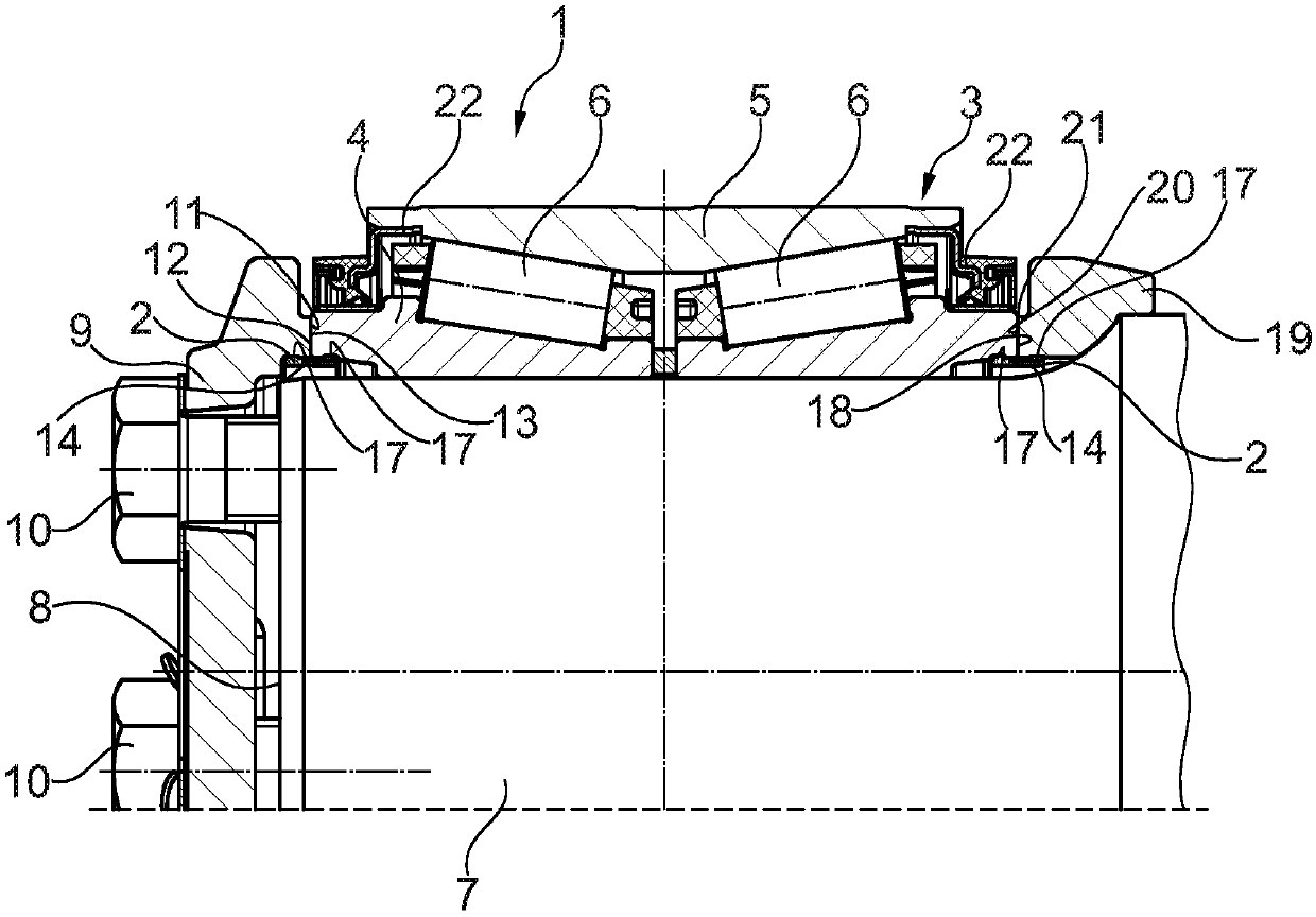
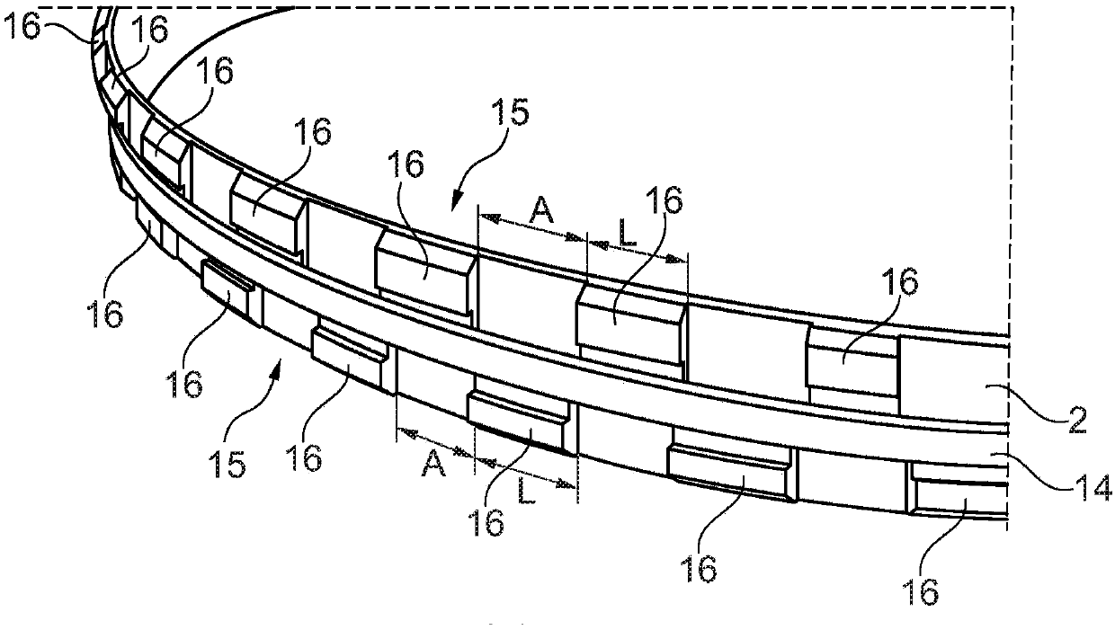
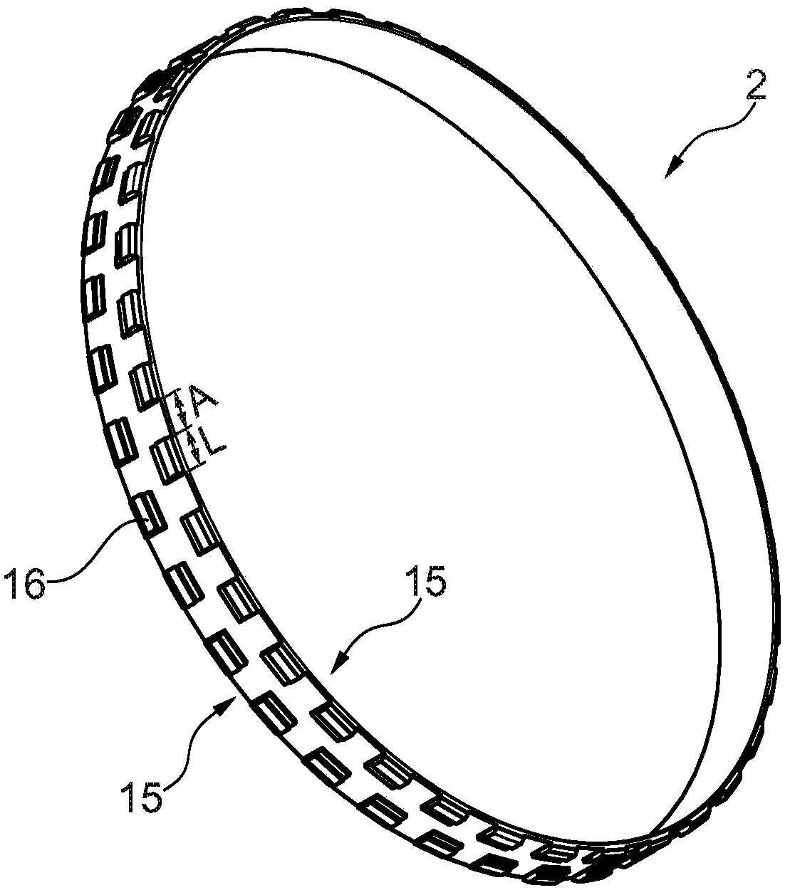
[0021] figure 1 An exemplary embodiment of a rolling bearing unit 1 with two retaining elements 2 is shown in a sectional illustration. The rolling bearing unit 1 shown comprises a rolling bearing 3 and two retaining elements 2 . The rolling bearing 3 has a multi-part bearing inner ring 4 , a one-piece bearing outer ring 5 and a plurality of rolling bodies 6 arranged in two rows radially between the two bearing rings 4 , 5 . In this embodiment, the rolling bearing 3 is designed as a two-row tapered roller bearing arranged in an O shape.

[0022] The multi-part bearing inner ring 4 is pressed onto the end of the wheel shaft 7 , wherein the wheel shaft 7 is designed as a solid shaft. The end side 8 of the wheel axle 7 is completely surrounded by an end cover 9 . The end cap 9 is connected in a rotationally fixed manner to the wheel axle 7 by means of a plurality of axially extending fastening elements 10 , in this embodiment by means of screws. The end side 11 of the end cap...


PUM


Abstract

The invention relates to a rolling-element bearing unit (1) for rail vehicles, comprising an inner bearing ring (4), an outer bearing ring (5), rolling elements (6) arranged between said bearing rings(4, 5), and at least one retainer element (2), said inner bearing ring (4) and the retainer element (2) being arranged on an axle (7), and the retainer element (2) being arranged radially between anaxial end of the inner bearing ring (4) and the axle (7), and radially between a contact part (9, 19) that lies against the end face (12, 18) of the inner bearing ring (4), and the axle (7), wherein at least one sealing element (14) is secured to the retainer element (2).

Description

technical field [0001] The invention relates to a rolling bearing unit for a rail vehicle according to the preamble of claim 1 . Background technique [0002] A rolling bearing unit for a rail vehicle generally comprises a rolling bearing with an inner bearing ring, an outer bearing ring and rolling elements located therebetween, wherein the rolling bearing is applied to the end of the wheel set shaft. An end cover is arranged on the end face of the wheel axle, which completely surrounds the end face of the wheel axle. The end cap bears against the end face of the bearing inner ring of the rolling bearing. A support ring is likewise arranged directly in contact with the other end face of the bearing inner ring. [0003] However, the wheel shaft is subjected to high rotational bending loads during operation, so that gaps are formed between the bearing inner ring and the support ring and between the bearing inner ring and the end caps, which close once per revolution and are...

Claims


Application Information

Patent Timeline
IPC IPC(8): F16C19/38F16C33/76F16C35/063B61F15/22
CPCF16C2326/10F16C2361/31F16C33/768F16C35/063F16C19/386B61F15/22B61F15/12
Inventor 克里斯托夫·马夸特
Owner SCHAEFFLER TECH AG & CO KG
Learn More