Blind corrugation end gland structure of container

A container and blind wave technology, which is applied in the field of containers, can solve the problem that the container blind wave end head structure does not have wire slots, etc., and achieve the effect of reducing the problem of wiring, reducing the overall quality, and improving the overall quality

Active Publication Date: 2018-03-09
靖江市亚泰特种材料制造有限公司
View PDF3 Cites 0 Cited by
  • Summary
  • Abstract
  • Description
  • Claims
  • Application Information

AI Technical Summary

Problems solved by technology

[0004] In view of the deficiencies in the prior art, the purpose of the present invention is to provide a container blind

Method used


Image

  • Blind corrugation end gland structure of container
  • Blind corrugation end gland structure of container
  • Blind corrugation end gland structure of container

Examples


Embodiment 1

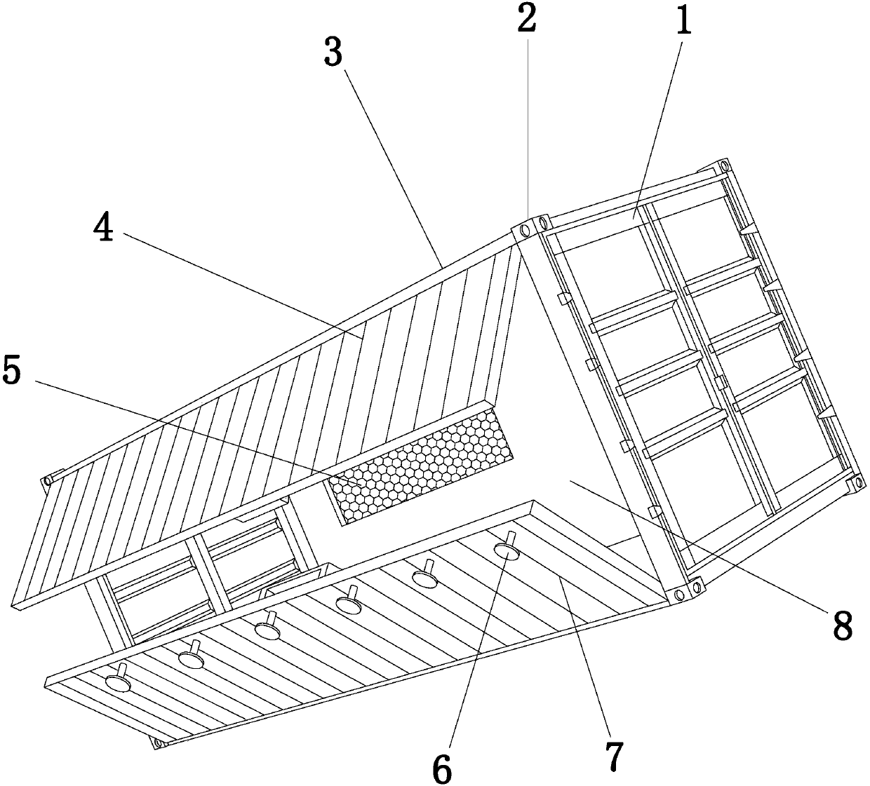
[0031] see Figure 1-Figure 7 , the present invention provides a container blind wave end head structure, which structure includes assembly door 1, blind wave end head 2, box body 3, No. 1 side sealing cover 4, sliding window 5, shock-absorbing auxiliary support feet 6 , No. 2 side seal cover 7, side wall panel 8;

[0032]The box body 3 has a rectangular structure and an assembly door 1 is provided at the front and rear ends, and the assembly door 1 is fastened and fixed on the box body 3, and the left side of the box body 3 is provided with a No. 1 side surface from top to bottom. Sealing cover 4 and No. 2 side sealing cover 7, described No. 1 side sealing cover 4 and No. 2 side sealing cover 7 are hingedly connected with casing 3, described No. 1 side sealing cover 4 and No. 2 side sealing cover 7 Matching, the outer wall of the No. 2 side sealing cover 7 is equidistantly provided with six shock-absorbing auxiliary supporting feet 6, and the described auxiliary shock-absorb...

Embodiment 2

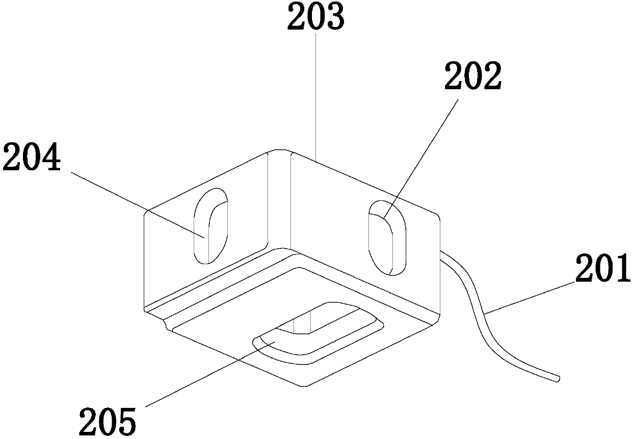
[0036] see Figure 1-Figure 8 The shock-absorbing auxiliary support foot 6 of the present invention is composed of bolts 601, hexagonal lock nuts 602, gaskets 603, load-bearing plate 604, and rubber body 605. The load-bearing plate 604 is a circular structure and the center position of the top is set There are bolts 601, and the bolts 601 are vertically fixed on the load-bearing plate 604, and three hexagonal lock nuts 602 are equidistantly arranged on the said bolts 601, and the said hexagonal locknuts 602 and the bolts 601 adopt clearance fit, so The washer 603 is fastened on the bolt 601 and matched with the hex lock nut 602 , and the rubber body 605 is tightly fixed on the bottom of the bearing plate 604 .

[0037] How the shock-absorbing auxiliary support foot works:

[0038] The shock-absorbing auxiliary supporting foot 6 bolt 601 is provided with a hexagonal lock nut 602 and a washer 603, and the bolt 601 can pass through the supporting foot mounting hole 702 on the No...


PUM


Abstract

The invention discloses a blind corrugation end gland structure of a container. The blind corrugation end gland structure comprises assembly doors, blind corrugation end glands, a container body, a No.1 side sealing cover, a sash window, damping assisting support legs, a No.2 side sealing cover and a side wallboard, wherein each blind corrugation end gland consists of a lead, a side hole, a high-strength metal frame, an end hole, a top hole and a trunking. The end holes, the side holes are the top holes are formed in the high-strength metal frames of the blind corrugation glands, so that splicing and dismounting can be facilitated, the overall quality of the container body can be improved, the design of the high-strength metal frames can adapt to torsion to prevent permanent deformation, the trunkings are arranged in the high-strength metal frames and communicated with the container body, the leads can be arranged in the container body conveniently, and reduction of the overall mass ofthe container body due to lead arrangement problem during manufacturing can be avoided.

Description

technical field [0001] The invention relates to a container blind wave end cap structure, which belongs to the field of containers. Background technique [0002] Container refers to a large-scale loading container with certain strength, rigidity and specifications specially used for turnover. Using containers to transship goods can be directly loaded in the consignor's warehouse and unloaded in the consignee's warehouse. When changing vehicles or ships midway, there is no need to take out the goods from the box for repacking. [0003] The prior art discloses a container blind wave end head structure with the application number: 03221893.1. The plate and the beam overlap, the plate adopts a blind wave plate, and the depression between the end of the blind wave plate and the beam overlap , filled with heads. The invention has a reasonable structure, solves the problem of difficulty in painting and gluing the depressions caused by the large amount of overlap between the corru...

Claims


Application Information

Patent Timeline
IPC IPC(8): B65D88/12B65D90/08B65D90/00
CPCB65D88/127B65D90/00B65D90/08
Inventor 朱礼鹏
Owner 靖江市亚泰特种材料制造有限公司
Why Eureka
Try Eureka