
Lubricating oil conveniently injected bearing pedestal

A technology of bearing seat and lubricating oil, which is applied in the direction of bearing components, shafts and bearings, lubricating parts, etc., can solve the problems of bearing seat damage, affecting production efficiency, and long injection time, so as to ensure the degree of lubrication and improve the use of efficiency effect

Inactive Publication Date: 2018-03-09
响水县冠龙轴承座制造有限公司
View PDF0 Cites 3 Cited by
  • Summary
  • Abstract
  • Description
  • Claims
  • Application Information

AI Technical Summary

Problems solved by technology

[0002] When the existing bearing seat is used, lubricating oil is continuously injected into the bearing seat from the opening of the oil injection part, and too much oil is often injected, causing too much oil to overflow from the gap between the bearing cover and the bearing core; the bearing Because it is difficult to check the amount of residual oil in the bearing seat, the timing of oil injection can only be controlled according to experience. If the oil is not filled in time, the bearing seat will be damaged, and it is necessary to stop the machine to add lubricating oil, and the bearing is often blocked. The oil groove in the bearing seat will make it very difficult to inject lubricating oil, and the injection time will be long, which will affect the efficiency of production

Method used


Image

  • Lubricating oil conveniently injected bearing pedestal
  • Lubricating oil conveniently injected bearing pedestal

Examples


Embodiment Construction

[0015] The following will clearly and completely describe the technical solutions in the embodiments of the present invention with reference to the accompanying drawings in the embodiments of the present invention. Obviously, the described embodiments are only some, not all, embodiments of the present invention.

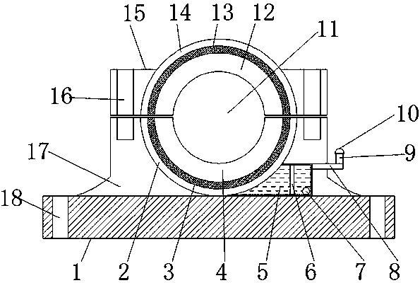
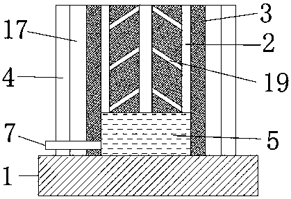
[0016] refer to Figure 1-2 , a bearing block for convenient injection of lubricating oil, including a seat cover 15, an upper bearing groove 13 is opened on the inner wall of the top end of the seat cover 15, and an upper annular oil groove 14 is opened on the inner wall of the upper bearing groove 13, and an upper annular oil groove 14 is opened on the inner wall of the upper annular oil groove 14 There is an arc-shaped oil groove 19, and the outer walls of both sides of the seat cover 15 are welded with limit rings 12, and the four corners of the top outer wall of the seat cover 15 are provided with engaging screw holes 16, and the engaging screw holes 16 are conne...


PUM


Abstract

The invention discloses a bearing seat convenient for injecting lubricating oil, comprising a seat cover, an upper bearing groove is opened on the top inner wall of the seat cover, and an upper annular oil groove is opened on the inner wall of the upper bearing groove, the inner wall of the upper annular oil groove is There is an arc-shaped oil groove, the outer walls of both sides of the seat cover are welded with limit rings, and the four corners of the outer wall of the top end of the seat cover are provided with joint screw holes, and the joint screw holes are connected with the top outer wall of the lower seat by bolts. A lower bearing groove is provided, and a lower annular oil groove is provided on the inner wall of the lower bearing groove. The present invention adds an oil storage box, and adds oil pipes and oil injection nozzles on the oil storage box, so that lubricating oil can be easily injected into the oil storage box without stopping the machine, and an observation window is added, which is conducive to observing the oil volume in the oil storage box and ensuring The amount of lubricating oil ensures the lubricating degree of the bearing, and increasing the annular oil groove and arc oil groove is conducive to the speed of lubricating oil diffusion and improves the use efficiency of lubricating oil.

Description

technical field [0001] The invention relates to the technical field of bearing seats, in particular to a bearing seat which is convenient for injecting lubricating oil. Background technique [0002] When the existing bearing seat is used, lubricating oil is continuously injected into the bearing seat from the opening of the oil injection part, and too much oil is often injected, causing too much oil to overflow from the gap between the bearing cover and the bearing core; the bearing Because it is difficult to check the amount of residual oil in the bearing seat, the timing of oil injection can only be controlled according to experience. If the oil is not filled in time, the bearing seat will be damaged, and it is necessary to stop the machine to add lubricating oil, and the bearing is often blocked. The oil groove in the bearing seat will make it very difficult to inject lubricating oil, and the injection time will be long, which will affect the efficiency of production. C...

Claims


Application Information

Patent Timeline
Patent Type & Authority Applications(China)
IPC IPC(8): F16C35/00F16N1/00F16N29/00
CPCF16C35/00F16N1/00F16N29/00
Inventor 杨燕燕
Owner 响水县冠龙轴承座制造有限公司
Learn More